Thin Films with Embedded Microspheres for Super-Resolution Microscopy
Introduction
Imaging by dielectric microspheres emerged as a surprisingly simple way of obtaining super-resolved images of nanoscale structures. The method implies bringing a dielectric microsphere in contact with the investigated structure so that the microsphere creates a magnified virtual image that can be viewed by a standard microscope at a certain depth inside the structure.
Based on a solid-immersion concept, the maximal diffraction-limited resolution available for high-index barium titanate glass (BTG) microspheres (ns ~ 2.0) can be estimated as λ/4. The optical super-resolution by high-index spheres should be defined as a resolution better than λ/4.
One of the well-known approaches for the experimental measurement of super-resolution values is based on using "point" objects. The image of such an object is defined as a point-spread function (PSF) of the optical system. The PSF width represents the system's optical resolution. The basic idea of this approach assumes that the resolution of the optical system is equal to the characteristic dimensions of the minimal feature sizes, which can be discerned in the optical images. This article shows that this approach can result in significantly overestimated resolution values.
Another direction of this research is related to a problem of field-of-view (FOV) limited by a quarter of the sphere diameter.
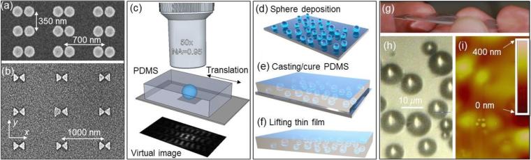
In this work, a different approach to this problem was developed, based on the incorporation of BTG spheres in intrinsically flexible, mechanically robust, and optically transparent polydimethylsiloxane (PDMS) thin films, as illustrated in Figure 1.
Fabrication: Nanoplasmonic objects and films with embedded spheres
As objects for imaging, arrays of Au dimers and bowties were used, which are illustrated by scanning electron microscopy (SEM) images in Figures 1(a) and 1(b), respectively. The fabrication of dimers was performed on a sapphire substrate by an electron beam lithography, metal evaporation, and liftoff process.
The BTG spheres with larger content of barium have an index ns ~ 1.9 and the spheres with larger content of titanium have an index ns ~ 2.1 for the red portion of the visible region. Imaging was performed by a scanning laser confocal microscope Olympus LEXT-OLS4000 operating at λ = 405 nm where the BTG microspheres with D ≤ 50 μm have negligible absorption. Due to glass dispersion, the index of BTG spheres with the excess barium content was estimated to be ns ~ 2.0 at λ = 405 nm providing index contrast with PDMS ~ 1.4 which is close to that for silica spheres in air.
To fabricate the coverslips with embedded spheres a three-step process was used that is schematically illustrated in Figure 1(d-f).
Use of coverslips without lubrication
It was found that the PDMS coverslips fabricated without any additional surface treatment were easily separable from the investigated samples. They can be completely peeled off from the sample resulting in freestanding PDMS films, which can be multi-used for super-resolution imaging on different samples.
Locomotion of lubricated coverslips
The lubrication was provided by using an easily evaporable liquid such as isopropyl alcohol (IPA) with an index of 1.37. A tapered stainless-steel microprobe inserted in the PDMS performed the locomotion of the coverslip.
The diffraction-limited resolution of the microscope objective can be estimated as d = 0.515λ/NA ~ 700 nm. However, experimentally, both the 700 nm and 350 nm periods of the arrays can be discerned in the virtual image. It can be explained by the fact that the microsphere, not the microscope objective, defines the angle θ of the microsphere-assisted imaging and higher effective NA values can be realized. Immediately after lubrication, however, the internal structure of the dimers, cannot be resolved through the microspheres even by using the 100 × (NA = 0.9) microscope objective lens.
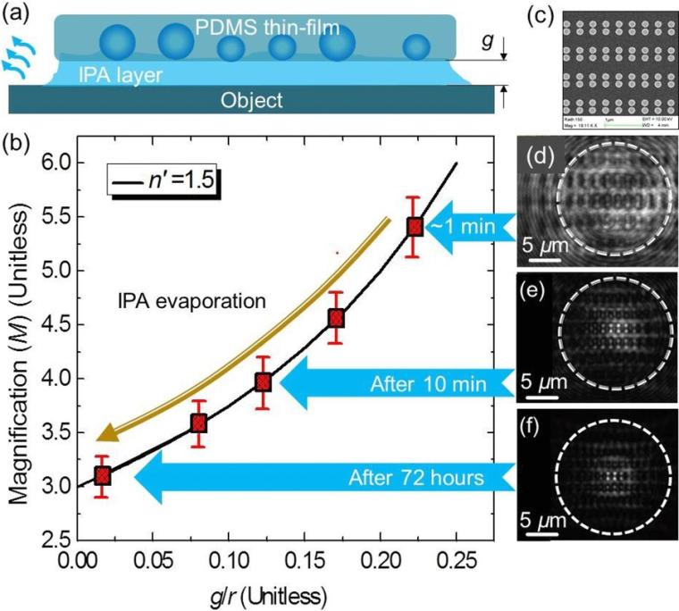
The dynamical behavior of M during the IPA evaporation was studied by the scanning laser confocal microscope Olympus LEXT-OLS4000 with the 100 × (NA = 0.95) objective lens at λ = 405 nm, as illustrated in Figure 2(d-f). For these studies, a rectangular array of Au dimers formed by the 185 nm cylinders with 65 nm edge-to-edge separations were selected. A similar array with smaller separations of about 15 nm is illustrated in Figure 2(c).
The magnification (M) of the virtual image created by the 16 μm sphere embedded in a PDMS coverslip was determined using a comparison with the real image of the surface of the structure outside the microsphere. The experimental results demonstrate a reduction of magnification from M ≈ 5.4 measured in the first minute after application of the coverslip (Fig. 2(d)) to M ≈ 3.1 after 72 hours (Fig. 2(f)). It should be noted that the M measurements are more precise in confocal mode compared to conventional microscopy because of the better in-depth resolution. This is determined by the much more compact axial FWHM of PSF in confocal microscopy available for the minimum detector apertures. Still, the small deviations from the optimal focusing depth led to the M measurement errors of about 5-6% illustrated by the vertical error bars in Figure 2(b). The measured M values were transported on the calculated M(g/r) dependence to estimate the gaps. Initially, for the first image obtained (Fig 2(d)) the gap was found to be 1.8 μm. After 10 minutes of IPA evaporation (Fig. 2(e)) the gap was reduced to 1 μm. After 72 hours (Fig. 2(f)) it appeared that the IPA layer had almost completely evaporated. The calculated gap values became less than 100 nm at this stage. The determination of a more precise steady-state value of nanoscale gaps was made difficult by the limited precision of the M measurements.
The resolution studies were performed in parallel with the magnification measurements using the same array of dimers and the same 16 μm BTG sphere, as shown in Figure 2(d–f). These dimers formed by 185 nm cylinders with 65 nm edge-to-edge separations were barely resolved within the first minute after lubrication and application of the coverslip (Fig. 2(d)). However, the structure of individual dimers became visibly better in the images obtained later in the course of evaporation of the IPA layer, even though the magnification was gradually decreasing (Figs. 2(e,f)).
These results show that the super-resolution provided by the embedded BTG microspheres gradually increases as the IPA layer evaporates. The resolution values obtained after 72 hours (λ/5.5) almost reached the level of resolution obtained in structures without lubrication (λ/6-λ/7).
Conclusion
Super-resolution imaging by dielectric microspheres has the potential to provide a strong impact on microscopy. It has been established that this method provides a superior image quality compared to the best diffraction-limited systems. It was shown that the observation of minimal discernible features in the optical images of extended objects (which cannot be approximated as point sources) could result in overestimated resolution values. It was also shown that a more consistent way of defining optical super-resolution is based on a standard procedure of convolution with PSF. This approach allows the development of unified resolution criteria, which can be used for comparing results obtained by different techniques.
Reference
Allen, K.W., Farahi, N., Li, Y., Limberopoulos, N.I., Walker, D.E., Jr., Urbas, A.M., Liberman, V. and Astratov, V.N. (2015), Super-resolution microscopy by movable thin-films with embedded microspheres: Resolution analysis. ANNALEN DER PHYSIK, 527: 513-522 https://doi.org/10.1002/andp.201500194.
Source: Image: Creative Commons