Super-Resolution Microscopy by Movable Thin Films with Embedded Microspheres
Microsphere-assisted imaging has emerged as a simple technique to obtain optical super-resolution. This work addresses the methodology of the resolution measurements and the limited field-of-view provided by each sphere. It is suggested that a standard method of resolution analysis in far-field microscopy based on convolution with the point-spread function can be extended into the super-resolution area. This provides a unified approach to resolution measurements. To develop surface scanning functionality, high-index barium titanate glass microspheres were embedded in polydimethylsiloxane (PDMS) thin films. It is shown that such films adhere to nanoplasmonic structures' surface so that the tips of embedded spheres experience the objects' optical near-fields.
Based on rigorous criteria, a resolution of approximately λ/6 – λ/7 (where λ is the illumination wavelength) is demonstrated for arrays of gold (Au) dimers and bowties. Such films can be translated along the surface of investigated samples after liquid lubrication. It is shown that after lubrication, the resolution is diffraction-limited; however, the super-resolution gradually recovers as the lubricant evaporates. It is shown that such films adhere to nanoplasmonic structures' surface so that the tips of embedded spheres experience the objects' optical near-fields. Based on rigorous criteria, a resolution of approximately λ/6 – λ/7 (where λ is the illumination wavelength) is demonstrated for arrays of gold (Au) dimers and bowties. Such films can be translated along the surface of investigated samples after liquid lubrication. It is shown that after lubrication, the resolution is diffraction-limited; however, the super-resolution gradually recovers as the lubricant evaporates.
Introduction
Imaging by dielectric microspheres has emerged as a surprisingly simple way to obtain super-resolved images of nanoscale structures. [1–9] The method involves bringing a dielectric microsphere in contact with the investigated structure so that the microsphere experiences the object’s optical nearfield and creates a magnified virtual image that can be viewed by a standard microscope. Initially, the method has been demonstrated for micrometer-scale, low-index (ns = 1.46) silica spheres in air. [1] After that, this method was advanced by using high-index spheres (ns > 1.8) submerged in a liquid or embedded inside elastomeric slabs, [3] which improved the quality of images. [4, 8]
Based on a solid-immersion concept, the maximal diffraction-limited resolution available for high-index (ns ~ 2.0) barium titanate glass (BTG) microspheres can be estimated as ~λ/4. Thus, the optical super-resolution by high-index spheres should be defined as a resolution better than ~λ/4. One of the well-known approaches to experimentally measure super-resolution values is using “point” objects. [10] The image of an object is defined as a point-spread function (PSF) of the optical system. The PSF width represents the system’s optical resolution. This concept is widely used in fluorescent (FL) microscopy, such as stimulated emission depletion (STED) [11] and other methods where bright “point” objects are readily available in the form of dye molecules or quantum dots.
To measure the resolution of microsphere-assisted imaging, researchers often select arrays containing features with recognizable shapes. [1–9] The basic idea of this approach is that the resolution of the optical system is equal to the characteristic dimensions of the minimum feature sizes that can be discerned. Different features have been studied by the microsphere-assisted technique that resulted in a broad range of resolution claims from λ/6 to λ/17. [1, 4–7, 9]
In this work, we show that this approach can result in significantly overestimated resolution values. To solve this problem, we developed a resolution analysis based on a standard procedure of convolution with PSF, with subdiffraction-limited values allowed. A similar approach has been used previously to provide one-dimensional (1D) treatment with rectangular functions. [8] In the pres ent work, we generalized this approach for 2D PSF and objects with arbitrary shape.
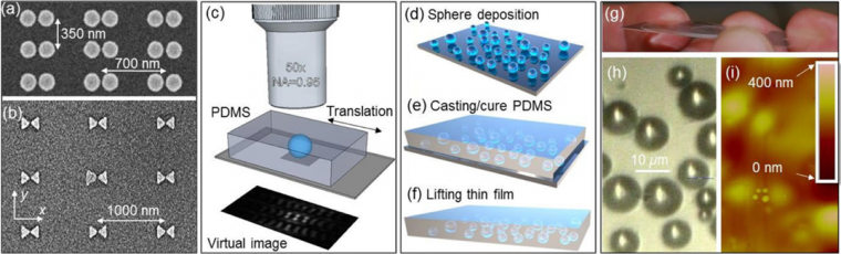
Furthermore, we developed a different approach to the field-of-view (FOV) limitations based on the incorporation of BTG spheres in polydimethylsiloxane (PDMS) thin films (or coverslips), as illustrated in Figure 1. The critical element of the coverslips’ design is a pla nar array of high-index BTG microspheres with a broad range of diameters (2 < D < 53 μm) held in the nanometer-scale proximity to the bottom surface of the coverslips. Once the coverslip is attached to a nanoplasmonic structure, the tips of microspheres can experience the object near-fields, leading to the possibility of super-resolution imaging. We show that the PDMS coverslips are naturally adherent to various substrates, providing imaging of Au dimers and bowties with ~λ/6 – λ/7 resolution. After surface lubrication with isopropyl alcohol (IPA), the coverslips can be translated along the surface. The ability to simultaneously capture images through the 2D array of spheres during wide-field microscopy allows precise alignment of microspheres with the objects of studies. We show that just after lubrication, the resolution is diffraction-limited. However, as the lubricant evaporates, the resolution gradually increases beyond the diffraction limit.
Methods
As objects for imaging, we used arrays of Au dimers and bowties illustrated by scanning electron microscopy (SEM) images in Figure 1a and Figure 1b, respectively. [8] The BTG spheres with larger barium (Ba) content have an index of ns ~ 1.9, and the spheres with a larger titanium (Ti) content have an index of ns ~ 2.1 for the red portion of the visible region. Imaging was performed by an Olympus® LEXT™ OLS4000 scanning laser confocal microscope operating at λ = 405 nm.
To fabricate the coverslips with embedded spheres, we used a three-step process [12] schematically illustrated in Figure 1d-f. This process bears some similarities with previously developed technology of embedding polystyrene microspheres in the PDMS membranes for applications in projection lithography. [13] First, the BTG spheres were deposited on the surface of a microscope slide, where they formed a disordered monolayer. Then, a PDMS layer was cast over the spheres. It was cured at 90 °C (194 °F) for one hour. The photograph of this layer at the top of the microscope slide is presented in Figure 1g. Finally, this thin layer was lifted from the substrate with tweezers and used as a coverslip in super-resolution studies.
Results and Discussion
The microsphere-assisted imaging demonstrates significantly improved resolution. The virtual image of a dimer in Figure 2a obtained through the 5 μm BTG sphere embedded in the PDMS coverslip is shown in Figure 2b.
The virtual image of a bowtie in Figure 2e obtained through the embedded 53 μm BTG sphere is shown in Figure 2f. Irradiance profiles along the x-axis of dimers and bowties are illustrated using red as color in Figure 2d and Figure 2h, respectively. The saddle-topeak ratios of these profiles, 0.16 and 0.35, respectively, are significantly smaller than that assumed in various classical definitions of resolution of two-point sources [14,15].
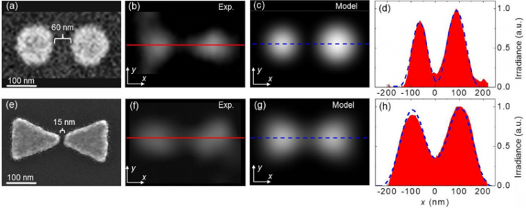
An attempt to define resolution based on the observation of minimal discernable features can lead to misleading results if, for example, we interpret the saddle point as a manifestation of a resolution of ~15 nm gap in bowties, which would imply a resolution above ~λ/27. As we show below, the image reconstruction with the Gaussian PSF with the width ~λ/5.5 allows obtaining a high-quality fit to the experimental results.
We treated the super-resolved images based on an analogy with the classical theory [16] where the image, I(x, y), is considered as a convolution of a diffraction-limited PSF and the object’s intensity distribution function, O(u, v). This can be expressed in the standard integral form by Equation 1:

in which the integration is performed in the object plane where the coordinates (xo, yo) are linearly related to the image plane via the magnification M as (x0, y0) = (xi/M, yi/M). We used a Gaussian function for PSF(x0, y0) with the full width at half maximum (FWHM) being a fitting parameter. Based on the Houston criterion, fitted values of the FWHM in the object plane were considered a resolution of the system. To enable the super-resolution analysis, we allowed subdiffraction-limited FWHM values; however, we kept the same basic Equation 1 for image reconstruction.
Images calculated with 2D PSFs with FWHMs ~λ/7 and ~λ/5.5 are presented in Figure 2c and Figure 2g for dimers and bowties, respectively. An excellent agreement with experimental images was found. Blue dashed lines represent the calculated intensity profiles along the x-axis. They are also found to be in good agreement with the experiment.
To align embedded spheres with various objects, we developed a technique based on lubrication and locomotion of the entire PDMS thin film containing BTG spheres, as illustrated in Figure 3. The lubrication was provided by using IPA with ns = 1.37. The locomotion of the coverslip was performed by a tapered stainless steel microprobe inserted in the PDMS connected with a hydraulic micromanipulation controller, providing ~1 μm precision of the translation.
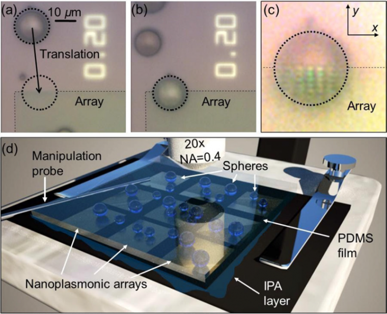
The translation and imaging through the coverslip immediately after its lubrication and application to the sample surface are illustrated in Figure 3a-c. Initially, the 16 μm BTG microsphere is located approximately 40 μm away from the border of the nanoplasmonic array (Figure 3a). As a result of the shift of the coverslip by ~40 μm, this sphere is aligned with the edge of the array (Figure 3b). The virtual image of the array was obtained by the 20 × (NA = 0.4) objective lens by focus ing deeper in the structure (Figure 3c). The diffraction-limited resolution of the microscope objective can be estimated as d = 0.515λ/ NA ~ 700 nm. However, experimentally, the 700 nm and 350 nm periods of the arrays can be discerned in the virtual image (Figure 3c). Immediately after lubrication, the internal structure of the dimers cannot be resolved.
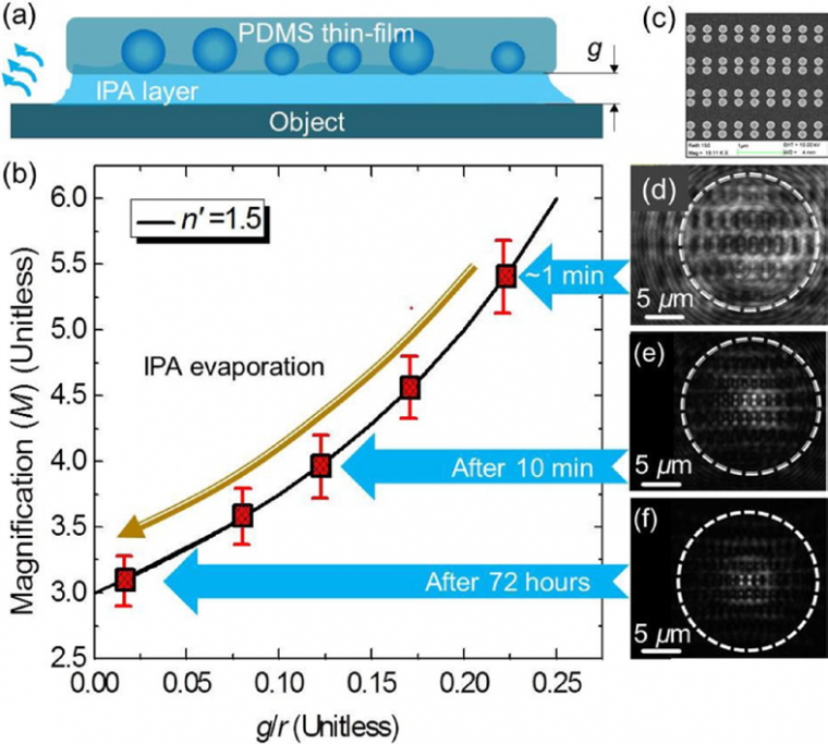
Achieving super-resolution in such a situation requires reducing the thickness of the IPA layer due to its evaporation, as schematically illustrated in Figure 4a. Using geometrical optics, it can be shown that the lateral image magnification (M) is related to the gap (g) separating the spheres from the object by Equation 2:

where r is the radius of the sphere, and n’ = nsp/n0 ∼ 2.0/1.37 ≈ 1.46 is the refractive index contrast between the sphere and object space. The dependence of M on the normalized gap (g/r) calculated using Equation 2 is illustrated for n’ = 1.5 by the black line in Figure 4b. In the limit of g << r, Equation 2 leads to |M| ~ |n;/(2-n’)| ~ 3. The dynamical behavior of M as IPA evaporates was studied (Figure 4d-f). The magnification (M) of the virtual image created by the 16 μm sphere embedded in a PDMS coverslip was determined using a comparison with the real image of the surface of the structure outside the microsphere [4]. The experimental results demonstrate a reduction of magnification from M ~ 5.4 measured in the first minute (Figure 4d) to M ~ 3.1 after 72 hours (Figure 4f).
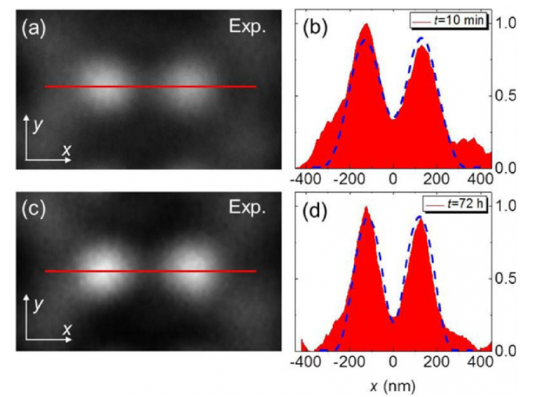
The dimers were barely resolved within the first minute after lubrication and application of the coverslip (Figure 4d). However, the structure of individual dimers became much bet ter visible in the images obtained later in the course of evaporation of the IPA layer, as seen in the magnified images after drying for 10 min and 72 hours (Figure 5a,c). Irradiance profiles along the x-axis of dimers are illustrated in Figure 5b and Figure 5d, respectively.
Using a PSF-based image fitting procedure described previously, we calculated intensity profiles along the x-axis, represented by blue dashed lines. They demonstrate excellent agreement with the experimental intensity profiles at the FWHM of the Gaussian PSF fitting function at ~λ/4 and ~λ/5.5. These results show that the super-resolution provided by the embedded BTG microspheres gradually increases as the IPA layer evaporates. The resolution values obtained after 72 hours (~λ/5.5) almost reached the level of resolution obtained in structures without lubrication (~λ/6-λ/7).
Conclusions
We showed that the observation of minimal discernible features in the optical images of extended objects (which cannot be approximated as point-sources) could result in overestimated resolution values. It is shown that a more consistent way of defining optical super-resolution is based on a standard procedure of convolution with PSF with widths smaller than the diffraction limit. We demonstrated that ~λ/6-λ/7 resolution could be systematically achieved in the images of nanoscale metallic dimers and bowties. Another bottleneck problem of this technology is based on a limited FOV of virtual imaging through individual spheres. In this work, we developed a technology of fabrication of transparent elastomeric PDMS thin films containing hundreds of embedded high-index BTG microspheres. Such films or coverslips can be considered as a new optical component for super-resolution microscopy.
References
[1] Z. Wang,W. Guo, L. Li, B. Luk’yanchuk, A. Khan, Z. Liu, Z. Chen, and M. Hong, Nat. Commun. 2011, 2, 218.
[2] X. Hao, C. Kuang, X. Liu, H. Zhang, and Y. Li, Appl. Phys. Lett. 2011, 99, 203102.
[3] V.N. Astratov, and A. Darafsheh. "Methods and systems for super-resolution optical imaging using high-index of refraction microspheres and microcylinders." U.S. Patent No. 9,726,874. 8 Aug. 2017.
[4] A. Darafsheh, G. F. Walsh, L. Dal Negro, and V. N. Astratov, Appl. Phys. Lett. 2012, 101, 141128.
[5] L. Li, W. Guo, Y., Yan, S. Lee, and T. Wang, Light: Science & Applications 2013, 2, e104.
[6] L. A. Krivitsky, J. J. Wang, Z. Wang, and B. Luk’yanchuk, Sci. Reports 2013, 3, 3501.
[7] H. Yang, N. Moullan, J. Auwerx, and M. A. M. Gijs, Small 2014, 10, 1712–1718.
[8] A. Darafsheh, N.I. Limberopoulos, J.S. Derov, D. E. Walker, Jr., and V. N. Astratov, Appl. Phys. Lett. 2014, 104, 061117.
[9] Y. Yan, L. Li, C. Feng, W. Guo, S. Lee, and M. Hong, ACS Nano 2014, 8, 1809–1816.
[10] S. Weisenburger and V. Sandoghdar, Contemporary Physics 2015, 56, 123–143.
[11] G. Donnert, J. Keller, R. Medda, M. A. Andrei, S. O. Rizzoli, R. Luhrmann, R. Jahn, C. Eggeling, and S.W. Hell, Proc. Natl. Acad. Sci. USA 2006, 03, 11440–11445.
[12] E. C. H. Sykes, S. P. Ashili, A. V. Kanaev, and V. N. Astratov, in IEEE Proceedings of OSA Topical Meeting on Informational Photonics, Charlotte, NC, 6-8 June 2005, paper No. IThD3.
[13] M.-H. Wu and G.M. Whitesides, Appl. Phys. Lett. 2000, 78, 2273–2280.
[14] A. Lipson, S. G. Lipson, and H. Lipson, Optical Physics, 4th Ed., (Cambridge University Press, New York, 2011).
[15] A. J. den Dekker and A. van den Bos, J. Opt. Soc. Am. A 1997, 14, 547–557.
[16] J. W. Goodman, Introduction to Fourier Optics, 2nd Ed., (TheMcGraw-Hill Companies, New York, 1996).
Copyright
DOI: 10.1002/andp.201500194; K. W. Allen, N. Farahi, Y. Li, N. I. Limberopoulos, D. E. Walker Jr., A.M. Urbas, V.Liberman, and V. N. Astratov; Annalen der Physik; © 2015 by WILEY-VCH Verlag GmbH & Co. KGaA, Weinheim
Source: Preview Image: Studio-Pro/iStockphoto