Breathable and Flexible Polymer Membranes with Mechanoresponsive Electrical Resistance
Flexible low-resistance membranes that tolerate very high deformability, produce low joule heating, and allow the passage of gases for human comfort are desired for wearable devices. Herein, a network of silver nanowires (AgNWs) between two highly porous electrospun thermoplastic polyurethane (TPU) membranes is presented. The membranes are mechanically robust (both for bending and stretching) and can withstand large strain before breakage (> 700%). The sheet resistance is as low as <0.1 Ω sq-1, and only increases to 1.6 Ω sq-1 upon stretching to 100% strain. The combination of polymer elasticity and the AgNW network structure provides a reversible change in resistance beyond 100% strain. This flexible, sandwich-like, electrically conductive membrane is a promising candidate for smart wearable devices and soft robotics.
Introduction
Traditional electronics are typically composed of intrinsically heavy and rigid materials, like silicon, metals, and glass, which have mini mal flexibility, stretchability, bendability, twistability, and impact resistance. There is a need for flexible and deformable circuits and electrodes with low electric resistance that maintain performance even in a strained state for lightweight, wearable, and flexible electronic devices. [1–3] Efforts to construct flexible circuits and electrodes with low resistance focused on elastomeric electrically conductive materials. [4–10] These materials are promising for a variety of applications; [11–17] however, obtaining flexible conductors with both high strain properties and low resistance is still a challenge. [18] Further, porosity is an essential requirement for the comfort of wearable electronic devices that contact skin to allow air for permeability.
Presently, flexible electrodes are composed of an elastic substrate, such as polydimethylsiloxane (PDMS), [19–20] thermoplastic polyurethane (TPU), [21] and electrically conductive materials. [22–26] Low-resistance electrodes provide the advantages of less energy loss and reduced joule heating. Silver is an excellent material for electrodes and is often used for flexible electrodes with low resistance. [27]
In our previous work, we prepared electrospun polymer membranes with a metal-like conductivity of 7.5 × 10⁵ S m-1 using a very low content (3.35 vol. %) of silver nanowires (AgNWs). [6] However, this kind of electrically conductive membrane is bendable but not sufficiently stretchable and is inherently nonporous.
Electrospinning is a promising technique for fabricating porous substrates with high conductivity, flexibility, and air permeability. The ability to electrospin many different polymer types also provides the advantage of tuning the membrane’s mechanical characteristics. For example, electrospun polyamide nanofiber nonwovens embedded with AgNW networks showed 50% stretchability and a sheet resistance of 8.2 Ω sq-1. [28] Electrospun polyurethane nonwoven porous substrate coated with AgNW provided a highly stretchable membrane (more than 300%) with high conductivity. [29]
Herein, we present a flexible and breathable polymer membrane with bending and stretching stability and very low electrical resistance. We also provide important fundamental studies on island formation, anisotropy, hot spots, and thermal transport in such structures. We present a simple and scalable preparation method for making such membranes. We use a network of AgNWs as conductive layer sandwiched between two porous electrospun TPU nanofibrous networks. We improved the interface stability with short polycaprolactone (PCL) fibers dispersed in between the AgNWs. Our membranes show a sheet resistance as low as <0.1 Ω sq-1. The resistance does not significantly increase upon deformation (twisting, bending, and stretching to approximately 100% strain). We also show a reversible change in the resistance upon stretching or bending with more than 100% strain for several cycles. The AgNW networks reversibly break and reform during stretching and releasing, respectively. These membranes are breathable, which allows the exchange of gases. Lastly, the membranes have a lower thermal conductivity compared to other porous polymers, despite their electrical conductivity. These membranes are a promising material for electrodes in smart textiles and other wearable devices.
Methods
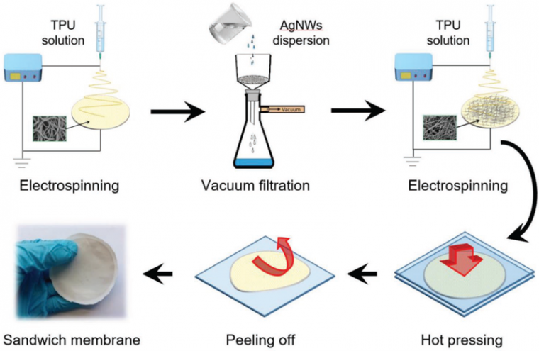
The concept for the preparation of flexible and breathable electrically conductive membranes is illustrated in Figure 1. First, we prepared TPU nanofiber nonwovens via electrospinning. We then used the porous TPU membranes as a filter for the filtration of AgNWs (17 mg mL−1, 126 ± 10 nm in diameter, and 18 ± 4 μm in length) mixed with a PCL short-fiber dispersion (1 mg mL−1, average aspect ratio ≈ 1000). Another layer of TPU nanofibers was electrospun on top of the AgNWs and PCL short fibers. To induce thermal annealing, the achieved sandwich-like, electrically conductive nonwovens were pressed between two glass plates and heated at a temperature of 75 °C (167 °F) for 30 minutes to melt the PCL fibers and bond the two lay ers of TPU nonwovens and AgNWs together.
A Zeiss LEO 1530 was used for scanning electron microscopy (SEM) characterization of the AgNWs and their corresponding networks. Energy dispersive X-ray analysis (EDX) was performed using a Zeiss Ultra Plus (V = 10 kV). Optical microscopy was performed using an Olympus LEXT OLS5000 confocal laser scanning microscope. A 100 × magnification lens with a working distance of 300 μm was used. Image analysis was conducted with Matlab. [30] The gas permeability test was performed with a homemade unit. [5] Tensile tests were carried out using a tensile tester (ZwickiLine Z0.5; BT1-FR0.5TN. D14). Sheet resistance measurements (four-point measurements) were performed using a Keithley 2420 high-current source meter coupled with a Signatone SYS-301. A digital multimeter (EMOS Multimeter EM391) connected to measure the sample with a bronze conduc tor was employed to measure the stretching resistance and bending resistance. Thermography imaging was performed with an Infratec VarioCAM HD research IR camera. Thermal diffusivity was measured with our own, self-built Lock-In thermography setup. [31-32]
Results and Discussion
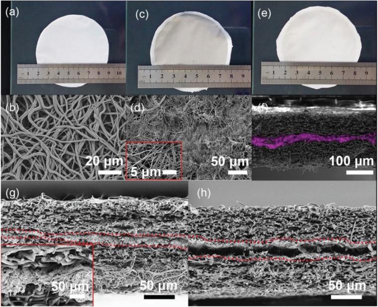
The TPU nonwovens consist of randomly oriented fibers (the 2D order parameter is around 0.1) with an average diameter of 1.6 ± 0.5 μm (Figure 2a,b). After filtration, the AgNWs and short PCL fibers generated a double network-type structure due to percolation (Figure 2c,d). Afterward, we covered the AgNW/ PCL layer with another layer of TPU nonwoven by electrospinning. Finally, we hot pressed the three-layer stack at 75 °C (167 °F) for 30 minutes to melt the PCL and increase the adhesion of the layers (Figure 2e).
The resulting three-layer membranes are designated as TPU-AgNW/PCL-TPU. We checked the presence of an AgNW layer sandwiched between the two TPU layers with PCL short fibers by EDX (Figure 2f). The cross-sectional SEM images of TPUAgNW/PCL-TPU and TPU-AgNW-TPU (without the use of PCL short fibers for comparison) are shown in Figure 2g,h, respectively. The PCL short-fiber dispersion acts as a glue between the AgNW network and the TPU. The TPU-AgNW/PCL-TPU membranes also possess good gas (CO2) permeability.
Different amounts of the AgNW dispersion were used to investigate the influence of the AgNW concentration on the air permeability and electrical properties. The sheet resistance was 6.1 ± 0.3 × 10⁸ Ω sq-1 without an AgNW layer. The sheet resistance decreased to 0.09 Ω sq-1 with 8.5 wt.% AgNWs. Even the use of a small amount of AgNWs (1.2 wt.%) significantly decreased the resistance to ≈ 1 Ω sq-1.
Further reduction in the amount of AgNW to ≈ 0.5 wt% led to a sharp increase in the sheet resistance (2.4 ± 3.1 × 10⁶ Ω sq-1). This result indicates that the percolation threshold of AgNW is 0.5 wt.% – 1.2 wt.%.
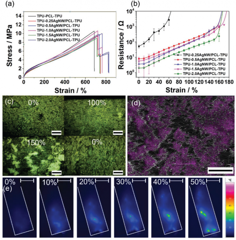
The sandwich membranes exhibited a breaking stress of ≈ 8 MPa. The TPU without AgNWs had breaking stress of ≈ 10 MPa. The membranes with different amounts of AgNWs can be stretched to over 700% (Figure 3a). The membranes showed 10% and 30% creep after stretching for 100 cycles to 50% and 100% strain, respectively. We measured the resistance as a function of % strain (Figure 3b).
TPU-AgNW/PCL-TPU can tolerate considerable strains with a moderate increase in resistance depending upon the amount of AgNWs. The sample with the highest content of AgNWs (8.5 wt.%) changed its resistance by only two orders of magnitude at a strain of ≈ 150%. In contrast, the sample with the fewest AgNWs (1.2 wt.%) showed a comparable increase in resistance already at a strain of only 60%.
Figure 3c shows the optical microscopy images of the AgNW layer after 0%, 100%, and 150% stretching and recovering to 0% again for the sample with 8.5 wt% AgNWs. When the membrane was stretched up to 100%, few cracks could be observed in the AgNW layer. However, upon further stretching to approximately 150%, large cracks (bright area), in an island-like fashion, were observed, causing a significant increase in resistance. The formation of island-like structures is confirmed by EDX measurement (Figure 3d). The separated islands and cracks restricted the flow of electricity and created hot spots due to joule heating at the bottlenecks. Such hotspots can be imaged by infrared thermography when applying a DC current (Figure 3e).
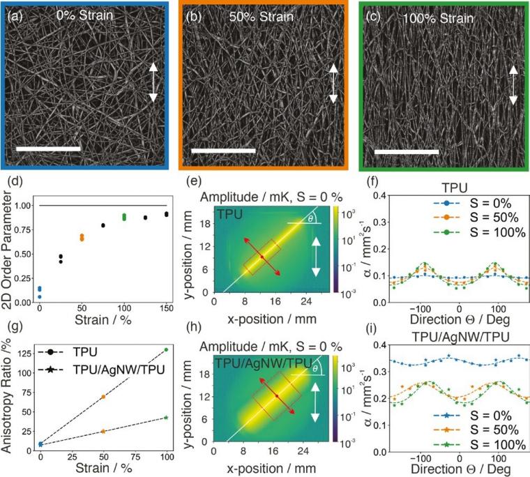
We employed direction-dependent lock-in thermography to gain a better insight into the composite morphology. Using a line laser as a heat source, we can probe the overall thermal diffusivity in such a composite sample along different orientations relative to the stretching direction. We see in Figure 4a–c that the TPU fibers align parallel to the stretching direction. Image analysis of these laser scanning microscopy images reveals that the fiber orientation is already complete at a strain of ≈100%.
The 2D order parameter (S2D) measures how well the fibers are aligned. The order parameter is given by Equation 1.

where N is the number of stretched fiber orientations in the SEM image, αi is the angle between the ith fiber and the horizontal axis, and α¯ is the average angle. [30] The S2D of pure TPU remains constant at a value close to 1.0 after 100% strain (Figure 4d). For pure TPU, the thermal diffusivity increases along the stretching direction and decreases perpendicular to it (Figure 4e,f). Since TPU is a thermal insulator, the absolute thermal diffusivity remains at a low level. Heat travels along these oriented fibers faster than perpendicular to it, resulting in a high anisotropy ratio (Figure 4g). For AgNW-TPU, some degree of anisotropy evolves (Figure 4h,i), but the overall thermal diffusivity decreases compared to the unstretched state. Simultaneously, for AgNWTPU samples, we find an evolution of anisotropic heat spreading (Figure 4g). Overall, the stretching of the AgNW-TPU sample leads to a smaller amount of anisotropy compared to the pure TPU network structure (Figure 4g).
The membranes showed excellent stretchability and bending stability. The samples were subjected to 100 cycles of stretching and bending. The resistance change (RC) can be described by Equation 2:

where R is the time-dependent resistance and R0 is the initial resistance measured after stretching and bending tests. The RC of the sample with 1.2 wt% of AgNWs significantly increased after only 60 stretching cycles; the RC was >20 000 under 50% strain. However, the same sample showed much better bending stability (bending curvature from 0° to 150°) without a significant change in resistance. The RC of TPU-0.25AgNW/PCL-TPU after 100 bending cycles was merely 1.32. The sample TPU-2.0AgNW/PCLTPU with a dense network of AgNWs showed both excellent bending and stretching stability. No significant change in the RC was observed for bending tests. During strain testing, RC increased by only a factor of ≈20 after 100 cycles.
Conclusions
In conclusion, we have demonstrated a new strategy to fabricate sandwich-like electrically conductive membranes with very low electric resistance. Our material consists of an AgNW network sandwiched between two porous electrospun TPU nonwovens. PCL short fibers act as glue and provide a robust interface between the three layers. Our membranes show excellent bending and stretching stability, high stretchability, and very low initial electric resistance (<0.1 Ω sq-1).
Additionally, the membrane possesses gas permeability and low thermal diffusivity. Furthermore, the material has the potential to be integrated into smart wearable devices.
References
[1] E. J. Markvicka, M. D. Bartlett, X. N. Huang, C. Majidi, Nat. Mater. 2018, 17, 618.
[2] Y. J. Hong, H. Jeong, K. W. Cho, N. Lu, D. H. Kim, Adv. Funct. Mater. 2019, 29, 1808247.
[3] S. Y. Huang, Y. Liu, Y. Zhao, Z. F. Ren, C. F. Guo, Adv. Funct. Mater. 2019, 29, 1805924.
[4] S. H. Jiang, S. Reich, B. Uch, P. Hu, S. Agarwal, A. Greiner, ACS Appl. Mater. Interfaces 2017, 9, 34286.
[5] Y. Zhou, C. J. Wan, Y. S. Yang, H. Yang, S. C. Wang, Z. D. Dai, K. J. Ji, H. Jiang, X. D. Chen, Y. Long, Adv. Funct. Mater. 2019, 29, 1806220.
[6] S. Reich, M. Burgard, M. Langner, S. Jiang, X. Wang, S. Agarwal, B. Ding, J. Yu, A. Greiner, npj Flexible Electron. 2018, 2, 5.
[7] Y. Q. Zeng, T. Li, Y. G. Yao, T. Y. Li, L. B. Hu, A. Marconnet, Adv. Funct. Mater. 2019, 29, 1901388.
[8] W. Weng, P. N. Chen, S. S. He, X. M. Sun, H. S. Peng, Angew. Chem., Int. Ed. 2016, 55, 6140.
[9] S. Lee, S. Shin, S. Lee, J. Seo, J. Lee, S. Son, H. J. Cho, H. Algadi, S. Al-Sayari, D. E. Kim, T. Lee, Adv. Funct. Mater. 2015, 25, 3114.
[10] J. Lee, B. L. Zambrano, J. Woo, K. Yoon, T. Lee, Adv. Mater. 2019, 1902532.
[11] R. Cao, X. J. Pu, X. Y. Du, W. Yang, J. N. Wang, H. Y. Guo, S. Y. Zhao, Z. Q. Yuan, C. Zhang, C. J. Li, Z. L. Wang, ACS Nano 2018, 12, 5190.
[12] M. Amjadi, M. Sitti, Adv. Sci. 2018, 5, 1800239.
[13] R. P. Tong, G. X. Chen, D. H. Pan, H. S. Qi, R. A. Li, J. F. Tian, F. C. Lu, M. H. He, Biomacromolecules 2019, 20, 2096.
[14] A. Chortos, J. Liu, Z. Bao, Nat. Mater. 2016, 15, 937.
[15] S. H. Wang, J. Y. Oh, J. Xu, H. Tran, Z. Bao, Acc. Chem. Res. 2018, 51, 1033.
[16] Y. Lee, J. Park, A. Choe, S. Cho, J. Kim, H. Ko, Adv. Funct. Mater. 2019, 1904523.
[17] C. Majidi, Adv. Mater. Technol. 2019, 4, 1800477.
[18] G. Chen, N. Matsuhisa, Z. Y. Liu, D. P. Qi, P. Q. Cai, Y. Jiang, C. J. Wan, Y. J. Cui, W. R. Leow, Z. J. Liu, S. X. Gong, K. Q. Zhang, Y. Cheng, X. D. Chen, Adv. Mater. 2018, 30, 1800129.
[19] T. H. Kim, C. S. Lee, S. Kim, J. Hur, S. Lee, K. W. Shin, Y. Z. Yoon, M. K. Choi, J. Yang, D. H. Kim, T. Hyeon, S. Park, S. Hwang, ACS Nano 2017, 11, 5992.
[20] H. S. Liu, B. C. Pan, G. S. Liou, Nanoscale 2017, 9, 2633.
[21] A. D. Valentine, T. A. Busbee, J. W. Boley, J. R. Raney, A. Chortos, A. Kotikian, J. D. Berrigan, M. F. Durstock, J. A. Lewis, Adv. Mater. 2017, 29, 1703817.
[22] H. H. Shi, N. Khalili, T. Morrison, H. E. Naguib, ACS Appl. Mater. Interfaces 2018, 10, 19037.
[23] N. Karim, S. Afroj, S. R. Tan, P. He, A. Fernando, C. Carr, K. S. Novoselov, ACS Nano 2017, 11, 12266.
[24] C. Zhu, A. Chortos, Y. Wang, R. Pfattner, T. Lei, A. C. Hinckley, I. Pochorovski, X. Yan, J. W. F. To, J. Y. Oh, J. B. H. Tok, Z. Bao, B. Murmann, Nat. Electron. 2018, 1, 183.
[25] M. Tavakoli, M. H. Malakooti, H. Paisana, Y. Ohm, D. G. Marques, P. A. Lopes, A. P. Piedade, A. T. de Almeida, C. Majidi, Adv. Mater. 2018, 30, 1801852.
[26] H. Lee, M. Kim, I. Kim, H. Lee, Adv. Mater. 2016, 28, 4541.
[27] P. C. Hsu, X. Liu, C. Liu, X. Xie, H. R. Lee, A. J. Welch, T. Zhao, Y. Cui, Nano Lett. 2015, 15, 365.
[28] Y. J. Fan, X. Li, S. Y. Kuang, Y. Kuang, L. Zhang, Y. H. Chen, L. Liu, K. Zhang, S. W. Ma, F. Liang, T. Wu, Z. L. Wang, G. Zhu, ACS Nano 2018, 12, 9326.
[29] Z. Jiang, M. O. G. Nayeem, K. Fukuda, S. Ding, H. Jin, T. Yokota, D. Inoue, D. Hashizume, T. Someya, Adv. Mater. 2019, 31, 1903446.
[30] N. E. Persson, M. A. McBride, M. A. Grover, E. Reichmanis, Chem. Mater. 2017, 29, 3.
[31] A. Philipp, N. W. Pech-May, B. A. F. Kopera, A. M. Lechner, S. Rosenfeldt, M. Retsch, Anal. Chem. 2019, 91, 8476.
[32] H. M. Akram, M. Maqsood, H. Rashid, Rev. Sci. Instrum. 2009, 80, 075103.
Copyright:
DOI: 10.1002/adfm.201907555; Qiang Gao, Bernd A. F. Kopera, Jian Zhu, Xiaojian Liao, Chao Gao, Markus Retsch, Seema Agarwal, and Andreas Greiner; Advanced Funtional Materials; © 2020 The Authors.
Published by WILEY-VCH Verlag GmbH & Co. KGaA, Weinheim
Source: Preview Image: argus/Shutterstock