Flexible Micropillar Electrode Arrays for In Vivo Neural Activity Recordings
Flexible electronics that can form tight interfaces with neural tissues hold great promise for improving the diagnosis and treatment of neurological disorders and advancing brain/machine interfaces. Here, the facile fabrication of a novel flexible micropillar electrode array (μPEA) is described based on a biotemplate method. The flexible and compliant μPEA can readily integrate with the soft surface of a rat cerebral cortex. Moreover, the recording sites of the μPEA consist of protruding micropillars with a nanoscale surface roughness that ensures tight interfacing and efficient electrical coupling with the nervous system. As a result, the flexible μPEA allows for in vivo multichannel recordings of epileptiform activity with a high signalto-noise ratio. The ease of preparation and high flexibility make the μPEA an attractive tool for in vivo spatiotemporal mapping of neural activity.
Introduction
Neural electrodes can be used to develop an understanding of brain functions and have become a clinical tool for the diagnosis and treatment of neurological disorders. [1–8] In particular, epilepsy is a common neurological disorder that affects about 1% of the general population and 4% of children. [9] Clinically, about 30% of patients with epilepsy respond poorly to antiepileptic drugs and have to undergo surgical resection of the epileptic foci. Subdual intraoperative electrocorticography (ECoG) has been routinely applied in patients with intractable epilepsy for both preoperative localization of the epileptogenic focus and assessment of post-surgical outcomes. [10–12] ECoG recordings are typically performed with subdural electrode arrays that are placed directly on a cerebral cortex’s surface. [13] Subdural electrodes are much less invasive than penetrating depth electrodes that cause tissue damage and elicit a pronounced foreign body response. [14,15]
The interfaces between electrodes and neural tissues play an essential role in recording neural activity because extracellular signals decay rapidly with distance. [16,17] A key challenge for creating tight interfaces between conventional subdural electrodes and neural tissues has been their sizeable mechanical mismatch. [18] The poor contacts between conventional rigid electrodes and soft tissues lead to the poor electrical coupling at their interfaces. As a result, neural activity signals can be notably attenuated by the cerebrospinal fluid in the electrode-tissue gaps. [19]
Flexible subdural electrodes based on polymer substrates have been developed to improve the contacts between electrodes and neural tissues. [20-25] In addition, they were shown to reduce the foreign body response of the brain tissue in chronic applications. [26] Nevertheless, the moduli of the polymer substrates are in MPa to GPa range, [27] which is still orders of magnitude higher than that of the brain. This can cause shear force and micromotion at the electrode-tissue interfaces, limiting the accuracy and stability of subdural ECoG recordings.
Here, we introduce a flexible subdural micropillar electrode array (µPEA) that enables the formation of tight neural interfaces and stable neural activity recordings. The recording sites of the µPEA consist of protruding microscale pillars with nanoscale roughness obtained by replicating the surface of a lotus leaf. The hierarchical surface structure affords lower impedance compared to planar electrodes. In addition, the protruding micropillars create a tight interface and effective electrical coupling between the electrodes and the cerebral cortex of a rat brain. As a result, the µPEAs have been successfully demonstrated for stable multichannel recordings of epileptiform activity with high SNR of 252 ± 35.
Methods
The fabrication process of a μPEA is illustrated in Figure 1. PDMS base was mixed with a curing agent and poured onto a lotus leaf and cured at 50 °C (122 °F) for 1 hour. After peeling off the lotus leaf, a PDMS negative template was obtained. The template was treated with oxygen plasma at 100 W for 5 minutes. Then, a polyimide (PI) mask with a 3 × 3 hole array was transferred onto the PDMS template. The PI mask/PDMS was heated at 140 °C (284 °F) for 30 minutes under a pressure of ≈20 kPa to increase their adhesion. A PI precursor solution was then spin-coated onto the PI mask/PDMS. The system was heated at 120 °C (248 °F) for 20 minutes for the removal of the solvent and then 200 °C (392 °F) for 30 minutes in a vacuum for curing. After peeling off the PDMS template, a PI substrate with spatially patterned micropillars was obtained. Planar electrode arrays (PEAs) were also fabricated for comparison.
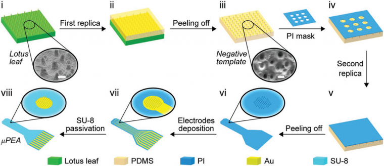
Neural electrode arrays were defined on a patterned PI substrate by thermal deposition of chromium/gold (Cr/Au) (10 nm/200 nm). The recording sites were aligned with the patterned micropillar regions of the PI substrate. Then a SU-8 passivation layer was defined by photolithography to encapsulate the planar interconnect lines. The μPEA was bonded to a flexible flat cable through anisotropic conductive film.
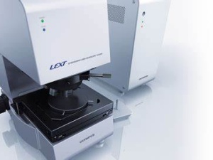
3D confocal images of the micropillar electrodes were acquired on a laser confocal microscope (Olympus LEXT OLS4000 system). Scanning electron microscopy (SEM) images were collected using a FEI Nova NanoSEM 430 system and Hitachi-SU8220. Cross-sections of the electrodes were obtained by focused ion beam (FIB) etching using a FIB/SEM dual-beam system. Electrochemical impedance spectroscopy (EIS) of the electrodes was measured using an electrochemical workstation (Reference 3000, Gamry Instruments). A Platinum (Pt) rod and an Ag/AgCl electrode (CHI111, CH Instruments) were used as counter and reference electrodes, respectively.
A Sprague-Dawley rat was anesthetized and fixed in a stereotaxic apparatus. Craniotomy was performed, and the left hemisphere was exposed, and the dura mater was carefully removed. A flexible μPEA was placed on the exposed subdural surface of the rat cortex. The neural signals were recorded at a sampling rate of 1 kHz.
Results and Discussion
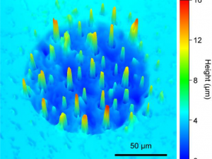
Figure 2a shows an as-prepared μPEA with a final thickness of 18 μm. The μPEA is highly flexible and can be bent repeatedly without loss of structural integrity. The μPEA consists of nine recording sites arranged in 3 × 3 matrices with 1 mm spacing (Figure 2b). Each recording site has a diameter of 120 μm (Figure 2c). SEM images of a typical electrode before and after SU-8 passivation are shown in Figure 2d. The enlarged SEM images in Figure 2e show that the micropillars contain nanoscale wrinkles. The height of the wrinkles ranges from 100 nm – 200 nm. 3D confocal images show that the μPEA consists of protruding micropillars (Figure 2f). Figure 2g shows a cross-sectional SEM image of a planar interconnects line, which consists of a three-layer sandwich structure of SU-8/Au/PI.
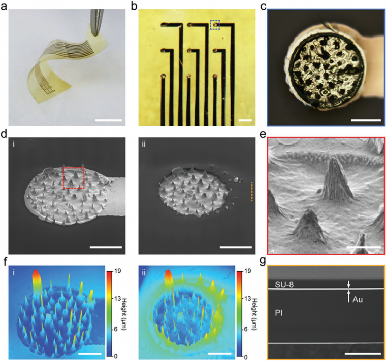
(ii) after passivation. Scale bars: 50 μm. e) Magnified SEM image of the area marked with dashed red box in insets (d-(i)). Scale bar: 10 μm. f) 3D confocal images of the electrode in inset (d-(i)) before and (d-(ii)) after passivation. Scale bars: 50 μm. g) Cross-sectional SEM image of the interconnect line marked with dashed orange line in inset (d-(ii)). Scale bar: 10 μm.
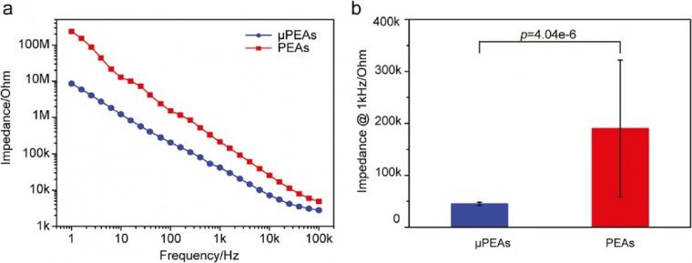
The performance of neural electrodes is mainly limited by the thermal noise that arises from the impedance at the electrode-electrolyte interface. [28] The impedance at the electrode-electrolyte interface is inversely proportional to the effective electrode area. We performed electrochemical impedance spectroscopy (EIS) on micropillar and planar electrodes on the same PI substrate for direct comparison. Figure 3a shows representative EIS results measured in phosphate-buffered saline (PBS). The impedance of the micropillar electrode is lower than the planar one. The reduced impedance can be attributed to the increased electrode area. Figure 3b summarizes the averaged impedance of 6 micropillar electrodes and 27 planar electrodes measured at 1 kHz.
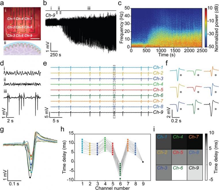
We applied the μPEAs for in vivo subdural recordings of penicillin-induced epileptiform activity in the rat cortex. As an antagonist of the gamma-aminobutyric acid (GABA) receptor, penicillin induces epileptiform activity by preventing GABA-mediated inhibitory control of pyramidal neurons. [29] As shown in Figure 4a, the μPEA conformally covered a large cortical area of the rat brain. Notably, the protruding micropillars at the recording sites were engulfed by the neural tissue, which resulted in significantly improved electrical coupling.
Figure 4b shows a representative real-time signal recorded by a micropillar electrode (Ch9), and Figure 4c is the normalized time-frequency spectral analysis of the time-series data. As shown in Figure 4d, three periods, including the basal period, latent period, and epileptiform activity period, could be identified.
The epileptiform activity period began with increasing discharges arising from the hyperexcitability and hypersynchrony of neuronal activity. As shown in Figure 4c, there was an associated increase in the spectral power between 5 Hz – 25 Hz. The amplitude of the discharges reached a maximum of 3.5 mV at 0.5 h after penicillin injection, and the μPEA allowed stable recordings over 3 h. The discharge frequency decreased from 0.8 spikes/s in the initial period to 0.2 spikes/s in the late epilepsy period. The high signal amplitude could be attributed to the tight interfaces and efficient electrical coupling between the protruding micropillars and neural tissue.
Figure 4e,f shows simultaneous multichannel recordings by the μPEA. We applied a thresholding method to detect epileptiform discharges recorded by the nine channels, from which spike times were extracted (Figure 4g). Spike-time delays at different channel locations were then calculated relative to the spike-time of Ch-9. Figure 4h summarized the spike-time delays of 50 epileptiform discharges recorded in a 255 s window. The spike-time delays show a clear dependence on the channel locations.
This allowed us to construct a pattern map by plotting the average spike-time delays as a function of each channel’s location (Figure 4i).
Conclusions
In summary, we demonstrated a facile biotemplate method for the fabrication of flexible μPEAs. The hierarchical surface structure of the μPEAs effectively reduced the impedance of the micropillar electrodes. Moreover, a tight electrode-neural interface was obtained due to the engulfment of the micropillars by neural tissues. As a result, the μPEAs allowed stable subdural recordings of neural activity with high SNR. Multichannel recordings further revealed the propagation characteristics of epileptiform activity across the cerebral cortex. These results show that flexible μPEAs can offer new opportunities to study the tempo-spatial dynamics of neural activities.
References
[1] P. K. Campbell, K. E. Jones, R. J. Huber, K. W. Horch, R. A. Normann, IEEE Trans. Biomed. Eng. 1991, 38, 758.
[2] J. L. Collinger, B. Wodlinger, J. E. Downey, W. Wang, E. C. Tyler-Kabara, D. J. Weber, A. J. C. McMorland, M. Velliste, M. L. Boninger, A. B. Schwartz, Lancet 2013, 381, 557.
[3] A. K. Engel, C. K. E. Moll, I. Fried, G. A. Ojemann, Nat. Rev. Neurosci. 2005, 6, 35.
[4] R. S. Fisher, A. L. Velasco, Nat. Rev. Neurol. 2014, 10, 261.
[5] C. M. Gray, P. E. Maldonado, M. Wilson, B. McNaughton, J. Neurosci. Methods 1995, 63, 43.
[6] G. Hong, R. D. Viveros, T. J. Zwang, X. Yang, C. M. Lieber, Biochemistry 2018, 57, 3995.
[7] J. J. Jun, N. A. Steinmetz, J. H. Siegle, D. J. Denman, M. Bauza, B. Barbarits, A. K. Lee, C. A. Anastassiou, A. Andrei, Ç. Aydın, M. Barbic, T. J. Blanche, V. Bonin, J. Couto, B. Dutta, S. L. Gratiy, D. A. Gutnisky, M. Häusser, B. Karsh, P. Ledochowitsch, C. M. Lopez, C. Mitelut, S. Musa, M. Okun, M. Pachitariu, J. Putzeys, P. D. Rich, C. Rossant, W.-l. Sun, K. Svoboda, M. Carandini, K. D. Harris, C. Koch, J. O’Keefe, T. D. Harris, Nature 2017, 551, 232.
[8] J. S. Perlmutter, J. W. Mink, Annu. Rev. Neurosci. 2006, 29, 229.
[9] A. T. Berg, C. P. Panayiotopoulos, Neurology 2000, 55, 1073.
[10] P. Jayakar, M. Duchowny, T. J. Resnick, J. Child Neurol. 1994, 9, 2S61.
[11] K. Lehnertz, C. E. Elger, Electroencephalogr. Clin. Neurophysiol. 1995, 95, 108.
[12] M. J. Morrell, Neurology 2011, 77, 1295.
[13] W. J. Freeman, L. J. Rogers, M. D. Holmes, D. L. Silbergeld, J. Neuro- sci. Methods 2000, 95, 111.
[14] R. Biran, D. C. Martin, P. A. Tresco, Exp. Neurol. 2005, 195, 115.
[15] P. J. Rousche, R. A. Normann, J. Neurosci. Methods 1998, 82, 1.
[16] G. H. Kim, K. Kim, E. Lee, T. An, W. Choi, G. Lim, J. H. Shin, Materials 2018, 11, 1995.
[17] E. W. Schomburg, C. A. Anastassiou, G. Buzsáki, C. Koch, J. Neurosci. 2012, 32, 11798.
[18] C. K. Im, J. M. Seo, Biomed. Eng. Lett. 2016, 6, 104.
[19] G. Buzsáki, C. A. Anastassiou, C. Koch, Nat. Rev. Neurosci. 2012, 13, 407.
[20] D. Khodagholy, T. Doublet, M. Gurfinkel, P. Quilichini, E. Ismailova, P. Leleux, T. Herve, S. Sanaur, C. Bernard, G. G. Malliaras, Adv. Mater. 2011, 23, H268.
[21] D. Khodagholy, J. N. Gelinas, T. Thesen, W. Doyle, O. Devinsky, G. G. Malliaras, G. Buzsaki, Nat. Neurosci. 2015, 18, 310.
[22] J.-H. Kim, G. Kang, Y. Nam, Y.-K. Choi, Nanotechnology 2010, 21, 085303.
[23] J. Viventi, D.-H. Kim, L. Vigeland, E. S. Frechette, J. A. Blanco, Y.-S. Kim, A. E. Avrin, V. R. Tiruvadi, S.W. Hwang, A. C. Vanleer, D. F. Wulsin, K. Davis, C. E. Gelber, L. Palmer, J. Van der Spiegel, J. Wu, J. Xiao, Y. Huang, D. Contreras, J. A. Rogers, B. Litt, Nat. Neurosci. 2011, 14, 1599.
[24] I. R. Minev, P. Musienko, A. Hirsch, Q. Barraud, N. Wenger, E. M. Moraud, J. Gandar, M. Capogrosso, T. Milekovic, L. Asboth, R. F. Torres, N. Vachicouras, Q. H. Liu, N. Pavlova, S. Duis, A. Larmagnac, J. Vörös, S. Micera, Z. G. Suo, G. Courtine, S. P. Lacour, Science 2015, 347, 159.
[25] Y. Guo, Z. Fang, M. Du, L. Yang, L. Shao, X. Zhang, L. Li, J. Shi, J. Tao, J. Wang, H. Li, Y. Fang, Nano Res. 2018, 11, 5604.
[26] J. W. Jeong, G. Shin, S. I. Park, K. J. Yu, L. Xu, J. A. Rogers, Neuron 2015, 86, 175.
[27] J. P. Seymour, F. Wu, K. D. Wise, E. Yoon, Microsyst. Nanoeng. 2017, 3, 16066.
[28] E. Huigen, A. Peper, C. A. Grimbergen, Med. Biol. Eng. Comput. 2002, 40, 332.
[29] R. L. Macdonald, J. L. Barker, Nature 1977, 267, 720.
Copyright
DOI: 10.1002/smll.201900582; M. Du, S. Guan, L. Gao, S. Lv, S. Yang, J. Shi, J. Wang, H. Li, and Y. Fang; small; © 2019 WILEY-VCH Verlag GmbH & Co. KGaA, Weinheim
Source: Preview Image: Sebastian Kaulitzki/Shutterstock