Effects of Multi-Scale Patterning on the Run-In Behavior of Steel – Alumina Pairings under Lubricated Conditions
The effect of multi-scale surfaces on frictional and wear performance was performed on a ball-on-disk tribometer under lubricated conditions using additive-free poly-alphaolefine oil. Multi-scale stainless steel samples (AISI 304) were prepared by micro-coining and subsequent, direct laser interference patterning. A comparison of different samples (i.e., polished reference, laser-patterned, micro-coined, and multi-scale) shows a clear influence of the fabrication technique on the tribological properties. For multi-scale structures, the structural depth from the micro-coining plays an important role. Multi-scale samples with lower coining depths (50 μm) showed an increased coefficient of friction compared to the purely micro-coined surfaces, whereas larger coining depths (95 μm) result in stable and lower friction values for the multi-scale patterns.
Introduction
Friction is a multi-scale phenomenon affected by various factors such as adhesion, deformation, fracture, and third-body interactions ranging from nanometer to millimeter scale. [1] This scale dependency is well known and manifests when measuring the coefficient of friction (COF) at the nano- and macro-scales. [2,3] The question that arises is how to overcome this multi-scale phenomenon and manipulate friction on different scales. Nature accomplishes this by creating hierarchical surface patterns. [1,4–6] In bio-mimetics, this design idea is used to create well-defined surfaces with specially tailored frictional properties. [7]
The tribological effectiveness, under dry and lubricated conditions, of single scale surface features has been demonstrated. [8–11] In terms of dry friction, the beneficial effects of surface structures can be mainly traced back to the storage of wear debris and a reduced contact area. [12,13] Under lubricated conditions, the improvements can be attributed to the storage of produced wear particles, [14] a reservoir effect for lubricants, [15] and hydrodynamic pressure build-up. [16]
There are various methods to manufacture artificial topographies with variable pattern parameters such as structural depth, pitch, diameter, or area density, including lithographic techniques, [17] embossing/coining, [18] and laser surface texturing. [19] Laser surface texturing and, in particular, direct laser interference patterning (DLIP) is a suitable technique to structure various materials with patterns having mm and even sub-mm features. [20] To produce larger feature sizes on metallic substrates, coining/embossing seems to be a viable process route, which also offers mass production capability. [21]
Despite the fact that nature demonstrates plenty of beneficial effects for multi-scale surface patterns, those patterns have been rarely investigated in terms of their frictional and wear behavior. Most of the tested patterns are “multi-shape” structures combining at least two pattern geometries with similar dimensions. Therefore, the goal of this research work is to investigate the frictional and wear performance of multi-scale surfaces combining a larger micro-coined surface pattern with a cross-like laser surface pattern (DLIP). The tribological behavior of the produced multiscale surface patterns is compared to single- scale micro-coined and laser patterns.
Methods
Stainless steel (AISI 304) blanks with a thickness of 1 mm (0.04 in.) and a polished surface (root mean square roughness Rq = 30 nm) were used. The samples were ultrasonically cleaned for 10 min. in cyclohexane, acetone, and then isopropanol.
Micro-coining is a forming process in which a pre-structured tool is used to imprint the tool's pattern into the surface of a workpiece. To coin high strength materials, the workpiece needs to be heated up to reduce the flow stress, decreasing the die load. The current density and heating time were set to 35 A mm-2 and 5 s, respectively. This leads to a maximum sample temperature of ~1200 °C (2192 °F). First, the sample is heated by conductive heating. Afterward, the sample gets cut and coined in one tool movement at 5 mm s-1. Circular dimples with structural depths of 50 μm and 95 μm, diameters of 181 μm and 212 μm, as well as a pitch of 558 μm, were fabricated (called A2 and A3, respectively). Polished reference samples were coined with a flat die keeping all coining parameters constant.
A high-power, solid-state, neodymium-doped (Nd) glass YAG laser with a pulse duration of 10 ns, a wavelength of 355 nm, and a repetition rate of 10 Hz was used for DLIP. The laser fluence was a constant 29 J cm-2 for all samples. By using two interfering sub-beams, linelike surface topography is induced. Well-defined, cross-like surface topography with a periodicity of 9 μm and a structural depth of 1 μm was obtained. To create the crosslike pattern, the samples are structured with two line-like patterns which are rotated by 90° relative to each other. Multiscale samples were first coined and subsequently superimposed by a cross-like laser pattern.
The samples' topography was characterized by laser scanning microscopy (Olympus LEXT OLS4100 laser scanning confocal microscope) to study the surface roughness and the quality of the patterns. The tribological tests were done using a ball-on-disc tribometer in rotational sliding mode with a constant normal force of 5 N and a track radius of 5 mm (0.2 in.). The tribological counter body was an aluminum oxide (Al2O3) ball with a diameter of 6 mm (0.24 in.). The estimated Hertzian contact pressure is ~1.29 GPa. The sample is located in a rotating lubricant containment filled with 7 mL of polyalphaolefine (PAO 40) oil. Linear variable differential transducers measured the friction force. A sliding velocity of 0.01 m s-1 was selected for this study.
Results and Discussion
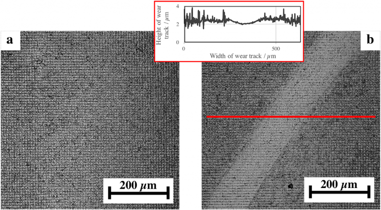
The coined surfaces are analyzed before and after DLIP using LSM. As shown in Figure 1c and Figure 1d, the small structures with a depth of ~1 μm created by DLIP are homogeneously distributed over the entire sample with features on the fillets between the dimples, as well as inside the dimples. The two different coined patterns are produced with the same die but varying coining pressures.
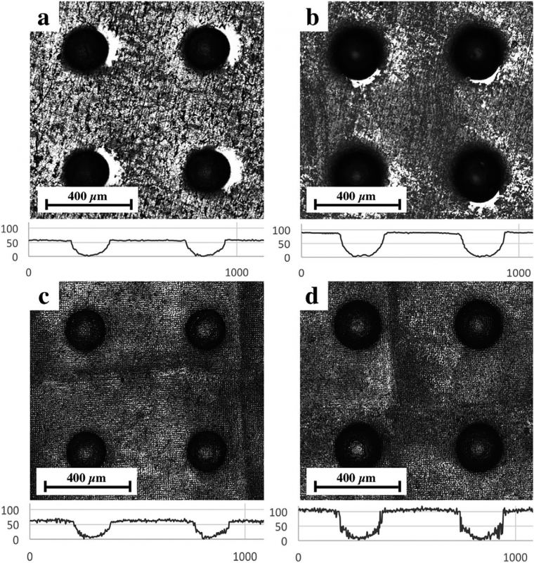
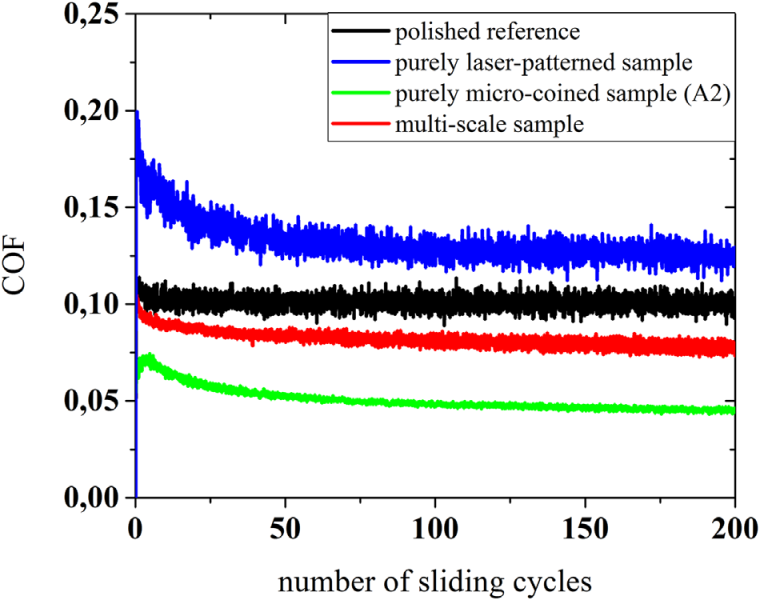
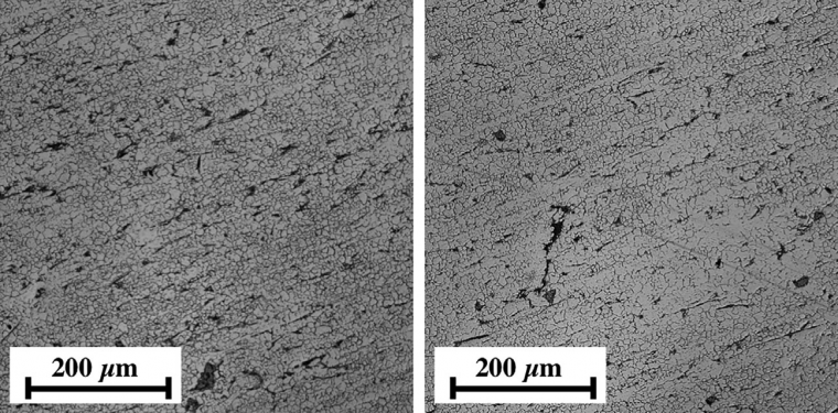
Figure 2 summarizes the COF's temporal evolution for the polished reference, the purely coined (A2), and laser-patterned samples. The figure shows the frictional behavior of the corresponding multi-scale sample (A2). The polished reference sample starts with a COF of ~0.11 and stays constant over the entire measuring time of 200 sliding cycles. The smooth trend of the COF, without any increase, combined with the fact that no pronounced wear tracks can be observed for the reference (Figure 3) at a sliding velocity of 0.01m s-1 leads to the conclusion that the prevailing lubrication regime can be assigned to elastohydrodynamic lubrication (EHL). This goes hand in hand with the estimated nominal Hertzian contact pressure of 1.29 GPa. This implies that elastic deformation of the rubbing surfaces and a viscosity increase with pressure become relevant. [22]
As can be seen in Figure 2, the COF of the laser-patterned sample starts at ~0.20 and decreases in the first 75 sliding cycles. Afterward, the sample reaches steady-state conditions. The observed effects can be attributed to the wearing-off of the highest surface asperities during the laser pattern's run-in and degradation. [10] The increased surface roughness and spiky surface topography increase the contact pressure, which makes a transition from full-film EHL to mixed lubrication. [8] Furthermore, the laser-patterned surface's load-bearing capacity is reduced compared to the plateau- like surface of the reference, which can also lead to more pronounced wear features and an increased wear rate. The laser pattern effects lead to the generation of wear particles and a modified contact area, which results in a higher COF over time. [23, 24]
The COF of A2 starts at ~0.07 and shows a slight increase in the first sliding cycles. This can be explained by an initial high wear rate in which the sharpest asperities are worn off. [25] After a decrease of the COF in the subsequent cycles, the COF remains relatively constant at ~0.05. Compared to the polished reference, A2 leads to a friction reduction by a factor of ~2. The significant friction reduction can be explained by a pressure build-up and an additional oil supply from the surface structures. [22]
As shown in Figure 2, the respective multiscale pattern (coining A2 and DLIP) shows worsened frictional behavior compared to the purely coined sample. The initial COF is ~0.10 and decreases to ~0.08. Compared to the polished reference, the multi-scale surface shows a ~20% decrease in COF. However, compared to the purely micro-coined surface, the COF of the multi-scale pattern is ~60% higher.
To explain the worsened frictional behavior of the multi-scale surface, the wear behavior of those samples needs to be examined. Figure 5 shows the entire wear track of the multi-scale surface (combining A2 and the laser pattern). The multi-scale surface shows a well-pronounced wear track. As a consequence, it can be assumed that the additional cross-pattern results in an increased contact pressure due to the rougher topography compared to the micro-coined samples. This can lead to undesired edge effects and stress raisers. Further, the alumina ball's deflection from its track is prominent, where it encounters several coined dimples in a row (see blue colored rectangle). The deflection of the ball might occur due to pressure build-up in the structures due to a converging gap that is formed between the ball and the structure.
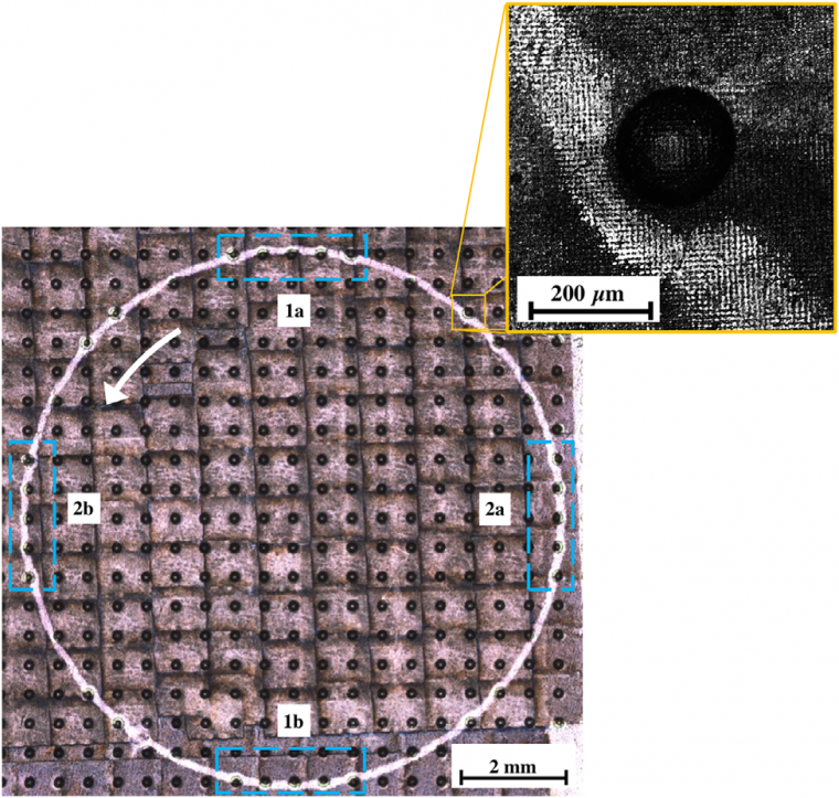
Figure 6 summarizes the temporal evolution of the COF of the reference, the purely coined (A3), the laser-patterned samples, and the multi-sale sample (A3 combined with laser-patterning). The initial COF of A3 is ~0.17 and then decreases to ~0.11. Com-pared to A2, the COF of A3 is greater. For the polished reference, the COF of sample A3 is significantly increased in the first 50 sliding cycles. In the following sliding cycles, the COF of the reference and A3 are rather similar. Surface structures with a larger structural depth have a higher probability for cavitation, thus reducing the oil film thickness and load-bearing capacity. [22,26]
The initial COF of the multi-scale surface is ~0.11. After a slight decrease in the COF, the COF remains constant at ~0.10. It can be assumed that the cross-pattern helps to reduce pronounced cavitation due to a better lubricant distribution in the contact zone. By reducing cavitation, a larger local oil film thickness can be present, improving the load-bearing capacity and reducing the COF.
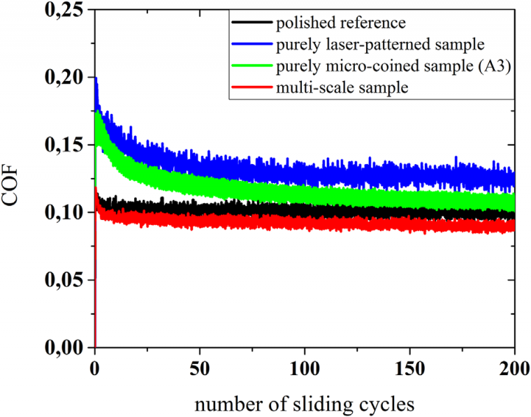
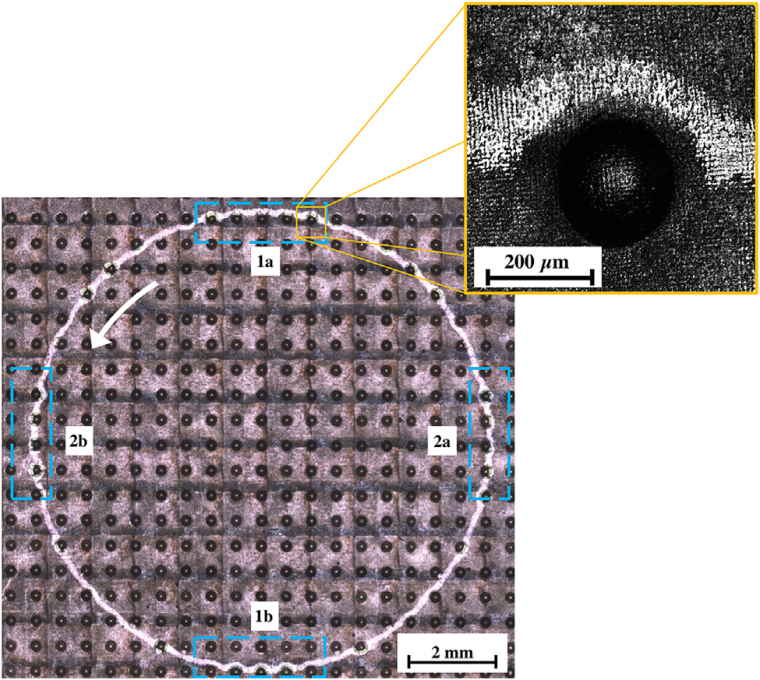
Figure 7 shows the wear behavior of the multi-scale pattern (A3 and laser-pattern) imaged by LSM. The deflection of the alumina ball from its track is prominent at the positions where it encounters several coined dimples in a row. Compared to the purely laser-patterned samples, the multi-scale patterns show a considerably reduced wear with a still intact laser-pattern after 200 sliding cycles. Wear behavior differences can be attributed to different lubrication regimes for the laser-patterned samples (mixed lubrication) and the multi-scale surfaces (mixed EHL).
Conclusions
To conclude, we found that the coined structures' depth determines whether the multiscale patterns have a beneficial or detrimental frictional effect. The COF of the multiscale pattern is decreased for deep structures (95 μm) and increased for shallower ones (50 μm). Further, laser-patterned samples show an increased COF due to the spiky surface topography, which increases the contact pressure and causes the transition from full-film EHL to mixed lubrication. For the purely microcoined surfaces, lower coining depths lead to the best tribological performance due to a pressure build-up in the lubricant and additional oil supply in the coined pockets. In contrast, the corresponding multi-scale sample shows worsened behavior due to increased surface roughness. The larger coined surfaces are less efficient over the entire measuring time because the deeper dimples are more prone to pronounced cavitation and do not allow for a sufficient pressure build-up. The multiscale surfaces show advantageous effects and are characterized by a stable and relatively low COF. The additional laser patterns help reduce cavitation and therefore contribute to enhanced lubrication in the contact zone.
References
[1] M. Nosonovsky, B. Bhushan, Mater. Sci. Eng. R Rep. 2007, 58, 162.
[2] E. Broitman, Friction 2014, 2, 40.
[3] J. R. Barber, Tribol. Lett. 2013, 49, 539.
[4] Z. Guo, W. Liu, B. L. Su, J. Colloid Interface Sci. 2011, 353, 335.
[5] B. Bhushan, Y. C. Jung, Prog. Mater. Sci. 2011, 56, 1.
[6] B. Bhushan, Philos. Trans. R. Soc. A Math. Phys. Eng. Sci. 2009, 367, 1445.
[7] H. Kasem, A. Tsipenyuk, M. Varenberg, Soft Matter 2015, 11, 2909.
[8] A. Rosenkranz, T. Heib, C. Gachot, F. Mücklich, Wear 2015, 334–335, 1.
[9] I. Etsion, Tribol. Lett. 2004, 17, 733.
[10] C. Gachot, A. Rosenkranz, L. Reinert, E. Ramos-Moore, N. Souza, M. H. Müser, F. Mücklich, Tribol. Lett. 2013, 49, 193.
[11] W. Tang, Y. Zhou, H. Zhu, H. Yang, Appl. Surf. Sci. 2013, 273, 199.
[12] A. Amanov, R. Tsuboi, H. Oe, S. Sasaki, Tribol. Int. 2013, 60, 216.
[13] B. Zhang, W. Huang, J. Wang, X. Wang, Tribol. Int. 2013, 65, 138.
[14] A. Kovalchenko,O. Ajayi, A. Erdemir, G. Fenske, Wear 2011, 271, 1719.
[15] A. Borghi, E. Gualtieri, D. Marchetto, L. Moretti, S. Valeri, Wear 2008, 265, 1046.
[16] D. Gropper, L. Wang, T. J. Harvey, Tribol. Int. 2016, 94, 509.
[17] U. Pettersson, S. Jacobson, Tribol. Lett. 2004, 17, 553.
[18] H. Ike, M. Plancak, J. Mater. Process. Technol. 1998, 80–81, 101.
[19] I. Etsion, J. Tribol. 2005, 127, 248.
[20] F. Mücklich, A. F. Lasagni, C. Daniel, Int. J. Mater. Res. 2006, 97, 1337.
[21] A. Szurdak, A. Rosenkranz, C. Gachot, G. Hirt, F. Mücklich, Key Eng. Mater. 2014, 611–612, 417.
[22] A. Rosenkranz, A. Szurdak, C. Gachot, G. Hirt, F. Mücklich, Tribol. Int. 2016, 95, 290.
[23] P. G. Grützmacher, A. Rosenkranz, S. Rammacher, C. Gachot, F. Mücklich, Tribol. Int. 2017, 116, 256.
[24] A. Rosenkranz, L. Reinert, C. Gachot, F. Mücklich, Wear 2014, 318, 49.
[25] P. J. Blau, Tribol. Int. 2005, 38, 1007.
[26] M. B. Dobrica, M. Fillon, M. D. Pascovici, T. Cicone, Proc. Inst. Mech. Eng. Part J J. Eng. Tribol. 2010, 224, 737.
Source: Preview image: Charles Schug/Getty Images