Stress Corrosion Cracking of Tempered 7xxx Alloys
Introduction
The high-strength Al-Zn-Mg-Cu alloys (7xxx series) have drawn considerable attention in the automobile industry in the past few years. This is due to their high strength (up to 600 MPa), light weight, and high resistance to corrosion.[1] However, one of the main problems is their high risk of susceptibility to stress corrosion cracking (SCC), which can lead to catastrophic failures in service.[2] Due to the complex nature of SCC, there is currently no common consensus on possible mechanisms.[3,4]
SCC is highly influenced by the nature and magnitude of stress. Consequently, the choice of loading systems for testing SCC can have a substantial impact on the test results.[5] The three commonly used stressing modes involve the application of a constant total strain, a constant load, and the use of a constant strain rate.
The aim of this work is to compare and critically analyze the advantages and disadvantages of the most common SCC test methods for the assessment of SCC in high-strength Al-Mg-Zn-Cu alloys. This work aims to understand the practicality of each test method with respect to automotive applications and analyze the influencing parameters that need to be considered when choosing an appropriate test method.
Materials and Methods
2.1 Materials
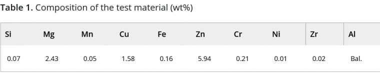
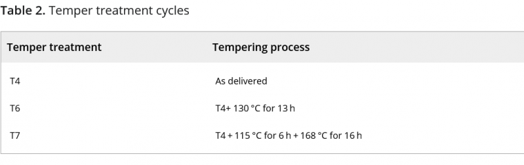
The material, whose composition is given in Table 1, was received in 300 × 300 mm[2] sheets of 1.5 mm thickness in three heat treatment conditions (Table 2).
2.2 Corrosion testing
2.2.1 Constant load test
The constant load test was carried out according to ASTM G47-98.[6] Standard A80 samples according to DIN EN ISO-6892-1:2017–02 were prepared by punching,[7] and they were uniaxially stressed to maintain a constant load corresponding to 75% of their yield strength.[6] Each stressed sample was subjected to alternating immersion testing in an aqueous NaCl solution according to ASTM G44-99 for a total duration of 30 days. A minimum of three trials were carried out for each material. The main analysis parameter considered was the time to failure. Fracture surfaces were analyzed using a scanning electron microscope to determine the nature of fracture. In addition, optical microscopy was carried out on fractured and unfractured samples.
2.2.2 U-bend test
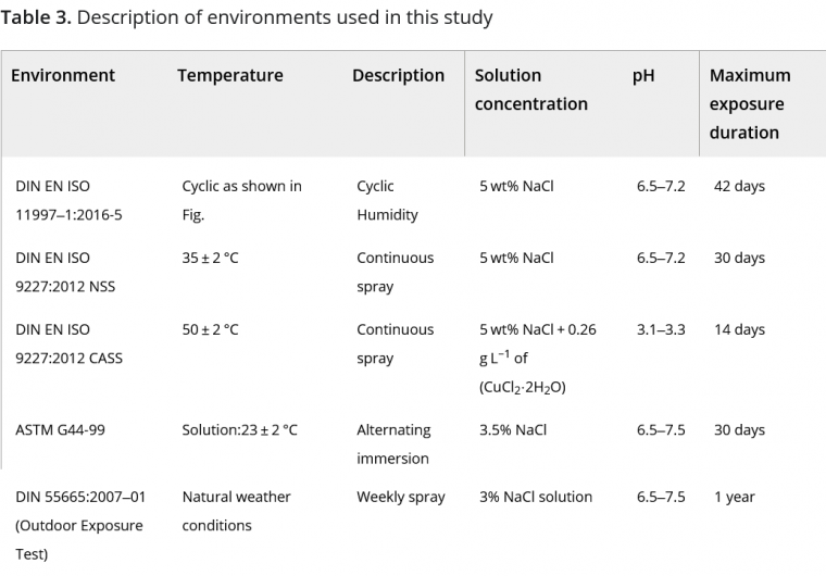
The U-bend sample preparation was performed according to ASTM G30-97.[8] U-bending samples were punched with an impact cutter and holes were drilled on either side. Spacers were used to ensure that bending did not exceed the final bend that was fastened. Once the samples were prepared, they were exposed to five environments for a definite period, or until failure of the sample. See Table 3 for details.
2.2.3 Four-point loaded bend test
The four-point loaded specimens were prepared according to ASTM G39-99.[9] Four-point bending specimen holders support the specimen at the ends and bend the specimens by forcing two inner supports against it. Once the samples were prepared, a minimum of three samples were exposed to two test environments, namely DIN EN ISO 11997- 1 Cycle B and ASTM G44-99 (Alternating immersion test).[10,11] The main analysis parameter considered was the time to failure. SEM fractographic analysis of the failed samples was carried out to determine the nature of the fracture.
2.2.4 Incremental step load test
In this test, specimens were subjected to an increasing step load cycle while being exposed to a test environment. The maximum load reached was used to compare the susceptibility of different alloys. One of the principal advantages of this test is that it always ends with a failure and does not need to be stopped after a specific duration. The setup of this experiment is similar to that of a constant load test, wherein an A80 sample is covered by a solution holder and uniaxially stressed. The test starts with a pre-load time of 96 h, in which the load is set to 50% of maximum load (load to failure). Thereafter, the load is increased every hour in steps of 5% of maximum force until the specimens fail. Throughout this load cycle, the sample is exposed to a test solution of 5% NaCl with an initial pH of 4, achieved by adding HCl to the solution. The minimum load to failure was compared to determine the SCC susceptibility ranking. SEM investigations as well as optical microscopy were carried out to determine the nature of the fracture surface.
2.3 Analytical methods
2.3.1 Optical microscopy
After the test exposure duration, the samples were cleaned, and cross-sections of each specimen type were prepared. These micro-sections were observed to determine the nature of the crack, the influence of other corrosion forms, and crack initiation sites. The microscopy was done using an Olympus® LEXT™ OLS4100 laser scanning digital microscope. The samples for each microstructural analysis were hot mounted under pressure with an epoxide resin. Subsequently, they were ground to 1200 level grit and then polished. The etching of the samples was carried out by dipping the specimen in 10% phosphoric acid for 30 min.
2.3.2 Scanning electron microscopy
Fracture analysis of failed specimens was performed using a scanning electron microscope (SEM) to determine the mode of failure and the nature of the fracture surface. The electron microscopy was performed with the MIRA Scan 3, from Tescan. A 10 V accelerating voltage was used for secondary electrons imaging.
Results and discussion
3.1 Characterization of materials
As expected, the T6 tempered alloy had the highest ultimate tensile strength and hardness. The electrical conductivity was seen to increase with annealing duration.
3.2 Constant load test
The constant load test was used as a standard reference for this study due to the experience and knowledge base in this test.
The results of the minimum time to failure for the constant load test, showed a clear influence of the temper treatment on the SCC susceptibility, with 7075-T4 being the most susceptible material, since it showed the fastest failure within 2 days of testing, followed by 7075-T6, which failed after 5 days of testing. The 7075-T7 alloy passed the 30-day test limit without failure.
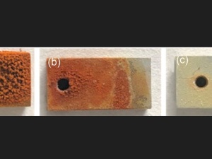
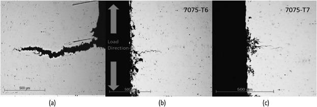
The metallographic examination of failed specimens revealed that the nature of the cracks was intergranular and multiple cracks were observed near the surface of the failure. Figure 1 shows the cross-section of the tested specimen. While 7075-T4 and 7075-T6 show localized corrosion influence, the 7075-T7 alloy shows crack initiation from an intergranular corrosion site.
Moreover, the SEM fractography of tensile tested samples in air revealed a ductile fracture surface with a typical honey-comb structure. In comparison, the fracture surface of the sample that failed during the SCC test showed an intergranular fracture surface, which is mostly brittle in nature. Primary cracks along with secondary branching are also visible on the surface. The failed sample of 7075-T6 alloy also showed a similar fracture surface, with a brittle quasi cleavage structure with primarily intergranular fracture surface.
These results indicate that the failure mechanism is intergranular in nature and correlate well with investigations by Schnatterer and Zander,[12] who got the same ranking of susceptibility using the SSRT test. They attributed the higher SCC susceptibility of 7075-T4 to the substantial IGC influence, due to anodic dissolution of the MgZn2 precipitates and lower SCC susceptibility of the over-aged alloy to incorporation of Cu to the grain boundary precipitates, resulting in an increase of their potential. Speidel et al.[5] also observed that over-aging (T7) greatly decreases the SCC susceptibility of high copper containing alloy, attributing it to formation of nobler Cu containing precipitates and, therefore, reducing anodic dissolution. However, a deeper understanding of this mechanism can only be obtained through TEM observations and grain boundary studies of the materials and the effect of tempering.
3.3 U-bend test
The 7075-T4 alloy underwent the earliest failure in all the corrosive environments as in the constant load test. It failed within a span of two days in all the considered environments. The failures of 7075-T6 were slightly delayed compared to the T4-treated samples in all the environments. The longest time observed for failure of this material was found for the alternating immersion test of 15 days. The 7075-T7 alloy showed no complete failure after the maximum duration of tests. However, it must be noted that samples of this temper from the alternating immersion test and the CASS test showed micro-cracks in optical microscopy.
The output of these results has direct correlation with the standard reference test. Comparing the time to failure of alloys in the different environments, the ranking of susceptibility is the same in all the environments. Interestingly, the correlation of the ranking produced by the fog tests, to the outdoor exposure test is also substantial. This good correlation of the climate tests to the outdoor exposure test shows a potential for the use of climate-chamber tests, which are a common practice test in automotive corrosion testing. The salt spray tests could be further developed to test SCC and potentially replace the alternating immersion test.
The DIN EN ISO 9227–2012 CASS test shows the highest corrosion influence of the four environments tested. This could be due to its acidic nature, higher temperature, the presence of higher chloride ions (due to presence of copper chloride), and due to the localized galvanic corrosion by copper ions. However, it is noticed in the micrographs and SEM fractographs that stress corrosion cracking, in this environment, is accompanied by severe forms of corrosion, especially intergranular corrosion. This makes it difficult to determine the exact cause of failure, deeming this environment inappropriate to test SCC.
Figure 2a shows the crack surface of the 7075-T4 alloy after 2 days of exposure to the neutral salt spray environment (DIN EN ISO 9227-2012 NSS). It represents the typical crack propagation direction observed in all the failed samples. Branching of the crack surface and multiple cracks are visible.
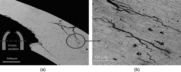
These cracks could also possibly be initiated before the cracks that led to failure. Hence, multiple cracks could lead to a significant relaxation of stress as compared to one propagating crack, leading to slower crack propagation and crack arrest. It can also be seen from the etched sample (Figure 2b) that the crack propagation is intergranular in nature. This factor could influence the results, while considering time to failure as primary criteria to qualify materials.
It is also observed that the crack initiates perpendicular to the surface and on further propagation changes its direction to parallel to the upper surface and arrests within the sample before failure. The U-bend sample has uneven stress distributions within the sample due to its high plasticity. Once a crack initiates in these regions, the stress distribution in the U-bend sample changes. The stress direction could also change, hence changing the crack path as well. This uneven change in stress distribution is an important factor to be considered in SCC testing.
3.4 Four-point loaded bend specimen
A comparison of the results of this test with the reference test, both in an alternating immersion environment, gives a clear difference in the effect of loading mode, since they were both stressed to 75% of the yield strength and exposed to the same environmental condition. The 7075-T6 alloy, in the constant load test, showed earliest failure after 5 days of exposure, whereas the same alloy in the four-point load bending test did not fail within 30 days of exposure. This could be attributed to the stress relaxation that occurs in the four-point load test on the initiation of the crack on the edges. On the other hand, crack initiation in the constant load test leads to the increase of stress on the remaining sample, leading to faster propagation of cracks and faster failure. This result agrees with the results of Brenner et. al. who also attributed the faster failure of the constant load test to stress concentration.[13]
During the four-point bending test, we observed that the failure crack was in the contact region of the roller and the specimen, rather than the expected region of the sample between the contact rollers where the stress is distributed. There are two possible factors for this behavior or the combination of both, that results in this cracking. The first factor is the frictional stress at the point of contact of the roller and the specimen as explained by Turnbull et al.[14] This failure adds unknown stresses to the induced stresses in the specimen. This error on the stress invalidates the advantage of knowing the exact stress to failure in this type of specimen. The second factor is the crevice corrosion that could take place at the contact point as mentioned in ASTM G39-99.[9] This crevice corrosion near the contact point is accompanied by an increase in hydrogen contents possibly leading to hydrogen included failure in this region. Since this is an uncontrolled process, it could lead to hindrance of the testing of SCC, and it becomes difficult to ascertain the parameters to failure.
3.5 Incremental step load test
The incremental step-load test is a novel test used in this study for testing the susceptibility of stress corrosion cracking of aluminum 7xxx alloys. The advantages of this test include the shorter timespan of the experiment of a maximum of 106 h, as compared to the other tests that ran up to 30 days or more. Another huge advantage of this test, as with the slow strain rate test, is that the test ends with failure for all the samples and does not need to be stopped at any arbitrary time, eliminating the uncertainty of whether the time ascertained for the test is appropriate. Although a practical application of incremental loading of stress may not be reasonable in real-world conditions, this test could be suitable for qualitative comparison of susceptibility of alloys by two factors, namely time to failure and maximum stress withstood. This gives a good qualitative ranking capability when alloys are to be compared. In this work, the results of the incremental step load test showed good agreement with the standard reference test.
The proposed mechanism taking place in this test is comparable to that of SSRT. Since SCC is a time dependent process, the aim of the pre-load time, in which the sample is exposed to the corrosive 5% NaCl solution and stressed at a load of 50% of the ultimate tensile strength, is to initiate stress corrosion cracking in the material, assuming that the stress is sufficient to do so. Once the crack is initiated after the pre-load time, the stress is increased and held in that stress state for a given time. The aim of this hold time is to induce SCC within the opened regions of crack, as in the slow strain rate test, producing then a complete brittle fracture. Since this is a load-driven test, the initiation of a crack would result in the increase of stress in the remaining specimen. This could lead to plasticity in the remaining region, hence, leading to a higher probability of stress corrosion cracking to occur. If the hydrogen induction mechanism is taken into consideration, the hydrogen atoms have time to be adsorbed into the open crack surface, and an increase of stress could increase the movement of hydrogen within the material by movement of dislocations. This induction of SCC would then differ with difference in susceptibility of materials, leading to failure of more susceptible alloys at lower stresses and vice versa, thus creating a ranking of the alloys.
The incremental step-load test considers two parameters to determine susceptibility of the alloy, namely the maximum stress withstood for the step loading and the time to failure. The 7075-T4 did not withstand the preexposure duration and failed after 48 h of exposure to 5% NaCl with a stress of 50% of the maximum load to failure (Fmk) followed by the failure of 7075-T6 at 63 h. The minimum load to failure ranged from 50% to 85%. The over-aged alloy did not show any susceptibility and passed the maximum load step of 95% Fmk. It is interesting to note, the correlation between these results to the other tests and the similarity of the ranking of the materials.
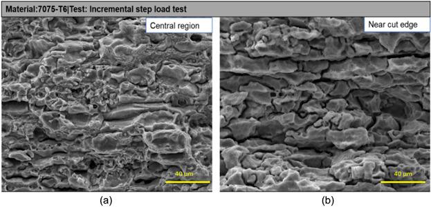
Figure 3 shows the fracture surface of 7075-T6 which failed at a stress of 55% Fmk, where Fmk stands for maximum load to failure. Two regions, one at the center of the specimen cross-section and another near the cut edge, show very different morphologies. The former shows both brittle and ductile areas. The region near the cut edge, however, shows a complete brittle intergranular cracking with branching. This difference in morphology could be attributed to the stresses present at the edges due to cutting. This could also explain the difference in failure stresses ranging from 50% Fmk to 85% Fmk. The embrittlement near the edges could be due to the effect of the plastic deformation of the edges due to punching, which causes substantial residual stresses on the specimen. The initiation of cracks due to this, could be uneven depending on the cut edges and these cracks could result in an overload on the rest of the material, once the crack is initiated from the edge. This explains the ductile regions visible in the center of the fracture specimen. In order to reduce the effect of cut edges, it is proposed that the test be optimized by use of milled or lasered specimens.
3.6 Critical analysis of the test methods
This work demonstrates the importance of loading mode and magnitude during SCC testing. Two specimens in constant total strain mode were examined: U-bend and 4-point loaded bend specimen. It was seen that the plastically strained U-bend test showed fast results as compared to the elastically 4-point bend test, due to a higher magnitude of stresses. However, the disadvantage of plastic straining is the complex calculation of stresses within the sample and uneven distribution of stresses. This inhomogeneous stress distribution does not allow for a quantitative determination of threshold stresses for SCC failure. It must also be considered that elastically strained specimens undergo stress relaxation once the crack initiates. The extent of this relaxation is dependent on the sample holder and the specimen size.[15]
On comparison of constant load and constant strain mode, the stress concentration increases, in a constant load mode, once the crack initiates. This makes the constant load test a more severe test. Multiple cracks were also observed in failed specimens, which could lead to inhomogeneous stress relaxation.[16] All the environments tested in this work were found to be sufficiently aggressive to cause SCC. The same susceptibility ranking was obtained in all the environments and the outdoor exposure test. However, each environment had different speeds of failure. The slowest was the alternating immersion test, which could be explained by absence of free atmospheric hydrogen ions present in the test, as compared to the salt spray fog test. The severest test was the CASS test, which could be attributed to its low pH, high temperature, higher chloride ions, and presence of Cu2+ ions, which could lead to localized galvanic corrosion. However, optical microscopy showed, that this test was highly influenced by other corrosion forms, such as intergranular and pitting corrosion. These other corrosion forms could have a substantial influence on the time to failure as well, making it an inappropriate test method to test SCC. A detailed analysis of the influence of pH, salt-content, temperature, and other environmental factors needs to be carried out in order to develop an appropriate SCC testing environment.
Conclusion
Four tests were conducted, compared, and critically analyzed to determine an SCC susceptibility ranking for differently tempered 7075 alloys. The following is a summary of the important observations and results obtained in this work.
1. Comparison of various environments used in this thesis showed that the acidic DIN EN ISO 9227:2012 CASS environment had the strongest corrosion influence on the tested materials. However, the SCC was also accompanied by other forms of corrosion, which could possibly affect the test results. The results of salt-spray tests, DIN EN ISO 9227:2012 NSS and DIN EN ISO 11997-1(B), showed that these tests can be appropriate substitutes for the standard alternating immersion environment. Since these test environments are well established in the automotive application, they have the potential to be further used for testing SCC susceptibility of 7xxx alloys for automotive application.
2. The U-bend test was easy to execute and economically viable. It also exhibited a good qualitative differentiability of SCC susceptibility of the 7075 alloy to SCC, which was confirmed by the correlation to the reference test as well as the outdoor exposure test.
3. The U-bend test showed fast results due to the large plastic strains on the specimen, hence, it is appropriate for an accelerated qualitative test. However, influence of stress relaxation and stress-redistribution due to crack formation must be thoroughly analyzed to use this test for commercial applications.
4. The U-bend test also shows a large dependence on sample preparation.
5. The four-point loaded bend samples did not produce a good differentiability of SCC susceptibility within the timeframe of the test. This was attributed to stress relaxation of the specimen on crack formation. Moreover, the failure of specimens was partly associated with crevice corrosion and frictional stress at the point of contact of the metal and stressing frame. These factors must be taken into consideration for further application of this test method. Possible improvements in this test could include concentration of the stress in the center of the specimen by means of notching or punching.
6. With the present parameters of the incremental step load test, it was seen that it was difficult to determine the cause of failure in this test. The test parameters were seen to have a substantial influence on the result. The optimization of the parameters, such as pre-load timing, step duration, different environmental parameters, and mill finished edges, could be beneficial for the future use of this method as an accelerated test for SCC susceptibility of 7xxx alloys.
7. The naturally aged 7075-T4 alloy showed the highest susceptibility in all the tests, followed by the peak-aged 7075-T6 alloy. The over-aged 7075-T7 alloy showed reduced susceptibility.
References
[1] Davis, J. R. Corrosion of Aluminum and Aluminum Alloys. (ASM International, 1999).
[2] Raja, V. S. & Shoji, T. Stress Corrosion Cracking: Theory and Practice. (Elsevier Science, 2011).
[3] Marichev, V. A. The mechanisms of crack growth in stress corrosion cracking of aluminium alloys. Mater. Corros. und Korrosion 34, 300–309 (1983).
[4] Burleigh, T. D. The Postulated Mechanisms for Stress Corrosion Cracking of Aluminum Alloys: A Review of the Literature 1980-1989. CORROSION 47, 89–98 (1991).
[5] Speidel, M. O. Stress corrosion cracking of aluminum alloys. Metall. Trans. A 6, 631–651 (1975).
[6] ASTM G47-98(2011). Standard Test Method for Determining Susceptibility to Stress Corrosion Cracking of 2xxx and 7xxx Aluminium Alloy Products. (1998) doi:10.1520/G0047-20.
[7] DIN EN ISO 6892–1:2017–02. Metallische Werkstoffe- Zugversuch- Teil 1. Prüfverfahren bei Raumtemperatur. (2017).
[8] ASTM G30-97(2016). Standard Practice for Making and Using Ubend Stress-Corrosion Test Specimens. (1997).
[9] ASTM G39-99 (Reapproved 2016). Standard Practice for Preparation and Use of Bent-Beam Stress-Corrosion Test Specimens. (1999).
[10] ASTM G44-99 (Reapproved 2013). Standard Practice for Exposure of Metals and Alloys by Alternate Immersion in Neutral 3.5% Sodium Chloride Solution. (1999).
[11] DIN EN ISO 11997-1:2016-05. Beschichtungsstoffe-Bestimmung der Beständigkeit (Salzsprühnebel)/trocken/feuchte. (2016).
[12] Schnatterer, C. & Zander, D. Influence of heat treatments on the stress corrosion cracking susceptibility of 7075 aluminum wires in NaCl solutions. Mater. Corros. 67, 1164–1172 (2016).
[13] Brenner, P. & Gruhl, W. No Title. Z. Met. 52, 599 (1961).
[14] Turnbull, A. & Crocker, L. E. Four point bend testing - finite element analysis of the stress and strain distribution. http://eprintspublications.npl.co.uk/6097/ (2014).
[15] Turnbull, A. Test methods for environment assisted cracking. Br. Corros. J. 27, 271–289 (1992).
[16] Richardson, T. J. A. Shreir’s Corrosion. (Elsevier Science, 2009).
Original article:
Magaji, N, Mayrhofer, R, Kröger, B, Schnatterer, C, Zander, D. Comparison of test methods used to analyze stress corrosion cracking of differently tempered 7xxx alloys. Materials and Corrosion. 2019; 70: 1192– 1204. https://doi.org/10.1002/maco.201810717
Source: Preview Image: daboost/Getty Images